TE & TM Modes
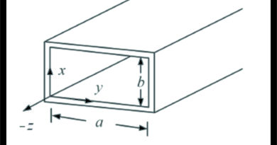
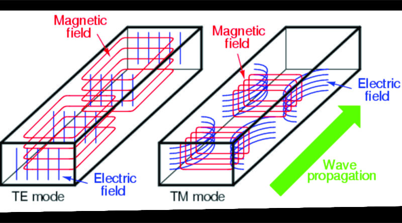
Electromagnetic waves travel down a wave-guide in different configurations called propagation models. These are two types of modes; TM modes (Transverse Magnetic) and TE modes (Transverse Electric). In TM modes magnetic lines are entirely transverse to the direction of propagation of EM wave. The electric field has a component in that direction. In TE mode (Transverse Electric), the electric field lines are entirely transverse to the direction of propagation whereas magnetic fields has a component along the direction of propagation Various propagation modes, both TM and TE, are designated by two subscripts m, n. The first subscript indicates the number of half-wave variations of the electric field in the wide dimension of the wave-guide whereas the second subscript indicates the number of half-ware variations of electric field along the narrow dimension (In case of TEmn mode). In TMmn, the same variation is for magnetic field. It may be mentioned that this subscript notations is only for rectangular wave-guides. In circular wave-guides, the subscripts are there but they do not carry the same meaning as they do in case of rectangular wave-guide.
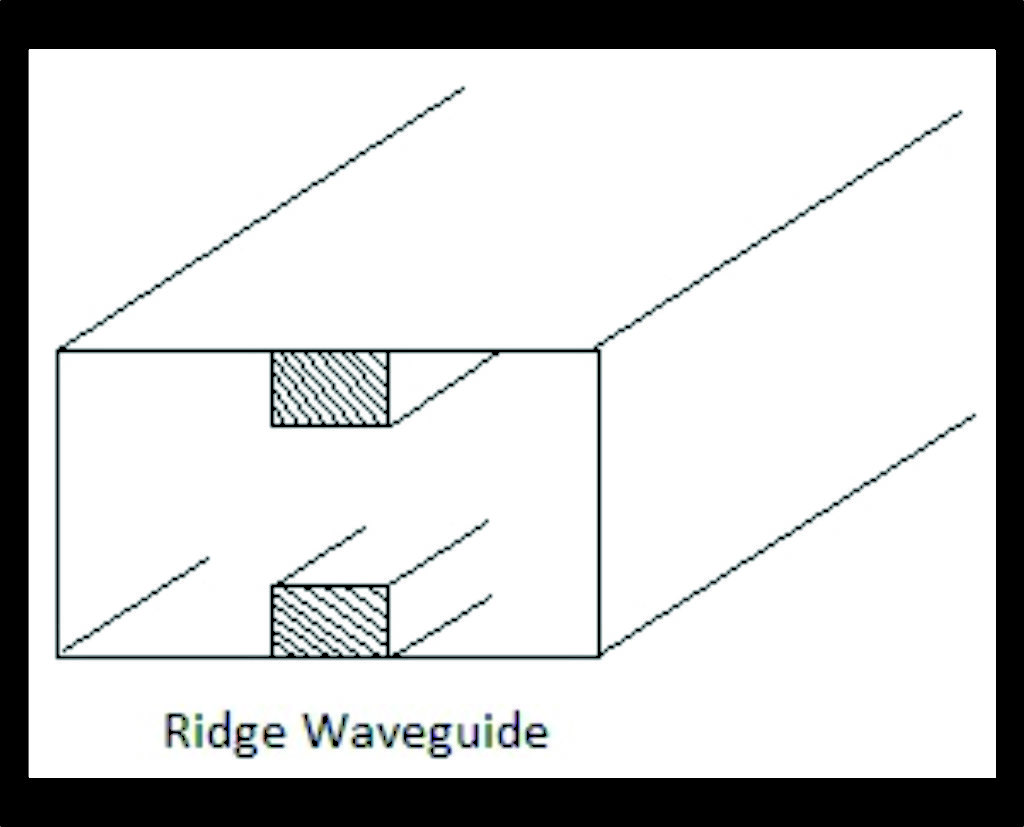
Ridged Wave-guide
A ridged Wave-guide may be constructed by adding a longitudinal metal strip to the top and / or bottom of a standard rectangular guide. The ridge acts as a uniform distributed loading and reduces the characteristic impedance of the wave-guide and lower the phase velocity. The reduction in phase velocity is accompanied by a lowering of the cutoff frequency of the TE10 mode by a factor that may be more than 5 to 1. At the same time, the cutoff frequency of the TE20 and TE30 modes is higher, depending on the ridge width. In this case, the ridge should be less than half the total dimension of the guide for the TE20 mode and between the one-third and two-third of the total dimension. This increase in bandwidth is accompanied. By an increase in the losses in the boundary walls and a decrease in power handling capacity. By suitable variations of ridge dimensions, it is possible to vary the characteristic impedance of the guide by a factor of 25 or more and increase the attenuation by several hundred. The ridge- wave-guide is useful in certain coupling and matching requirements since the characteristics impedance can be changed easily by gradually tapering the ridge.
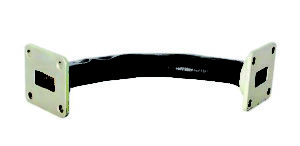
Flexible Wave-Guide
It is sometimes to have a wave-guide section capable of movement.
1) They may be bending, twisting, stretching or vibration, and this must not cause under deterioration in performance.
2) The applications depend upon the several types of flexible wave-guide.
3) Let copper or aluminum tube having an elliptical cross-section. These transform the TE, mode in the flexible wave-guide into the TElo mode at either end (having rectangular wave-guide). This wave-guide is of continuous construction, and joints and separate bends are not required. It may have a polyethylene or rubber outer cover and bends easily but cannot be readily twisted.
4) Power handling ability and SWR are fairly similar to there of rectangular wave-guides of the same size but attenuations in dB//m is about five times as much.
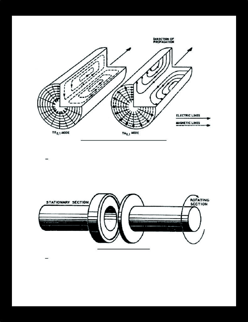
Circular Wave-guide
The circular wave-guide is used in many special applications in many special applications in microwave techniques. The circular guide has the advantage of greater power- handling capacity and lower attenuation for a given cut-off wavelength, but it has the disadvantage of somewhat greater size and weight. Also the polarization of the transmitted wave can be altered due to minor irregularities of the wall surface of the circular guide, whereas the rectangular cross section definitely flies the polarization. The wave of lowest frequency or the dominant mode in the circular wave-guide is the TE, I mode. The subscripts, which describe the modes in the circular wave-guide, are different than for the circular wave-guide. In the first subscript m indicates the number of full-wave variations of the guide. The second subscript in indicates the number of half-wave variations across a diameter.
Microwave Resonators
A cavity resonator sometimes cause a resonant cavity or wave meter, is a dielectric region completely surrounded by conducting walls. So a cavity resonator is a short segment of wave-guide that acts a high-Q parallel resonant circuit. A simply cavity resonator can be formed with a short piece of wave-guide one-half wavelength long as illustrated. A small probe at the center injects microwave energy. The short piece of wave-guide is closed at each end with a metallic short the result is that when microwave energy is injected into the cavity, the signal will bounce off the shorted ends of the wave-guide and reflect back toward the probe, because the probe is located a quarter wave length from each shorted end. The reflected signal will reinforce the signal at the probe. The result is that the signal will bounce back and forth off the shorted ends. If the signal is removed, the wave will continue to bounce back and forth for a continuous length of time until losses cause it to die out. This effect is pronounced at a frequency where the length of the wave-guide is exactly one-half wavelength. The cavity is said to resonate and acts like parallel resonant circuit. A brief burst energy applied to the probe will cause the cavity to oscillate until loses cause it to die out. Cavities such as this have an extremely high Q, as high as 30000. For this reason, they are commonly used to create resonant circuits and filters at microwave frequencies.