WAVE GUIDE
Principle of Wave Guide
Wave guide is a hollow conducting tube used to guide the electromagnetic waves from one place to another”. At frequencies of approximately 1GHz and above, the ability of cable (coax or other type) To carry energy decreases effectively and quickly, and above 18 to 20 GHz, coax is generally not usable except for very short distances (a few centimeters or inches). The high losses and attenuations in the cable from skin effect and radiations result in little of the initial energy reaching the load, even if the line is to load match is perfect. Also, it is difficult to transfer large mounts of power, because the voltages that occur at high power levels will break down the dielectric barrier between conductors (so very wide spacing is required). An alternative to cable is the wave-guide. A wave-guide is a hollow conductive tube, usually rectangular in cross section, but some times circular or elliptical. The dimensions of the cross section are selected such that electromagnetic waves can propagate within the interior of the guide (hence) the name Wave-guide. A wave-guide does not conduct current in the true sense, but rather serves a boundary that confines electromagnetic energy from their surface. If the wall of the wave-guide is a good conductor and very thin, little current flows in the interior walls and, consequently, very little power is dissipated. In a. Wave-guide, conduction of energy does not occur in the walls of the wave-guide, but rather through the dielectric within the wave-guide which is usually dehydrated air or inert gas. In essence, a waveguide is analogous to a metallic wire conductor with its interior removed. Electromagnetic energy propagates down a waveguide by reflecting back and forth in a zigzag pattern.
Warning Never look into a wave-guide or stand in front of the open end unless you know that the other end is disconnected, or the associated electronics system is off and cannot be switched on by someone else. Waveguide can carry large amounts of high frequency / short wavelength electromagnetic energy, and this energy radiation can cause’ eye damage, genetic damage, and other temporary or long terms injury. Be careful, double check, keep safety in mind.
Comparisons of Wave-guide & Transmission Line
1) Frequency Limitation Transmission lines (two-wire or coaxial line) are used to transfer energy of the low frequency signal. Above 3000 MHz, transmission lines are fails to transfer maximum energy. Wave-guides are used at such a high frequencies.
2) Attenuation There is a less attenuations in signal when guided through a wave-guide (above 3000 MHz) but attenuation is most effective in transmission lines.
3) Spurious Radiations At high frequencies, the signal which is transmitted through two-wire-transmission line, it radiates energy, however in wave-guides, due to skin effect, the signal concentrate to the inner surface of the waveguide and hence the possibility of radiation is eliminated.
4 ) Power Handling Capacity When a signal propagates in a wave-guide, a voltage exists between the walls of the guide the maximum power that can be transmitted in a wave-guide is limited by voltage breakdown. The power handling capacity of a wave-guide is much more than transmission lines (three to ten times).
Construction of Rectangular & Circular Wave-guide
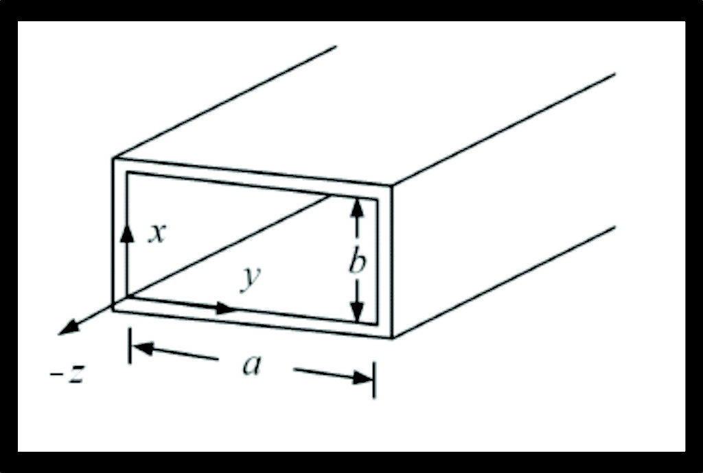
Rectangular Wave-guide
Assume that two wire parallel lines. The quarter wave stubs are attached to the top and bottom of a two-wire line and that such stubs are infinite in number and close enough to each other to touch. In such an instance the tubular section is formed, since the infinite number of quarter wave sections from the solid walls.
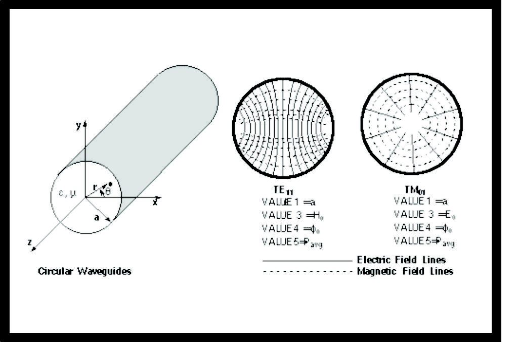
Circular Wave-Guide
This wave-guide is different with rectangular wave-guide in geometry. This wave-guide is formed by the quarter wave A/4 stubs which are circular in shape so the infinite numbers of these stubs form the circular shape called circular wave guide. It is to be noted that the diameter of the circular wave guide is one half-wavelength A/2 for the lowest frequency signal.
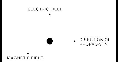
Consider the wave-guide as a hollow conducting tube to restrict the electric and magnetic fields. Propagation of the field energy is from one end to the other within the wave-guide. Propagation of EM wave through a wave-guide is by the reflection from the metal walls allow the energy to be propagated along the length.
The angle of incident and reflection depend upon the operating frequency. At high frequencies, the angles are large, and, therefore, the path between the opposite walls is relatively long. As the operating .frequency gets lower, the angles decrease and path between the sides shortens. When the operating frequency reaches the cutoff frequency of the wave-guide, the signal will simply bounce back and forth directly between the sidewalls of the wave-guide and will have no forward motion. At the cut-off frequency and below, no energy is propagated.