AC Waveform and AC Circuit Theory
Alternating Current (AC) forms the backbone of modern electrical power systems, powering everything from household appliances to industrial machinery. Unlike Direct Current (DC), which flows in one direction, AC periodically reverses direction, creating a waveform that oscillates between positive and negative values. This fundamental characteristic makes AC the preferred choice for power transmission and distribution worldwide.
Understanding AC waveform and circuit theory is essential for electrical engineers, technicians, and anyone working with electrical systems. This comprehensive guide will take you through the fundamental concepts, mathematical representations, and practical applications of AC circuits.
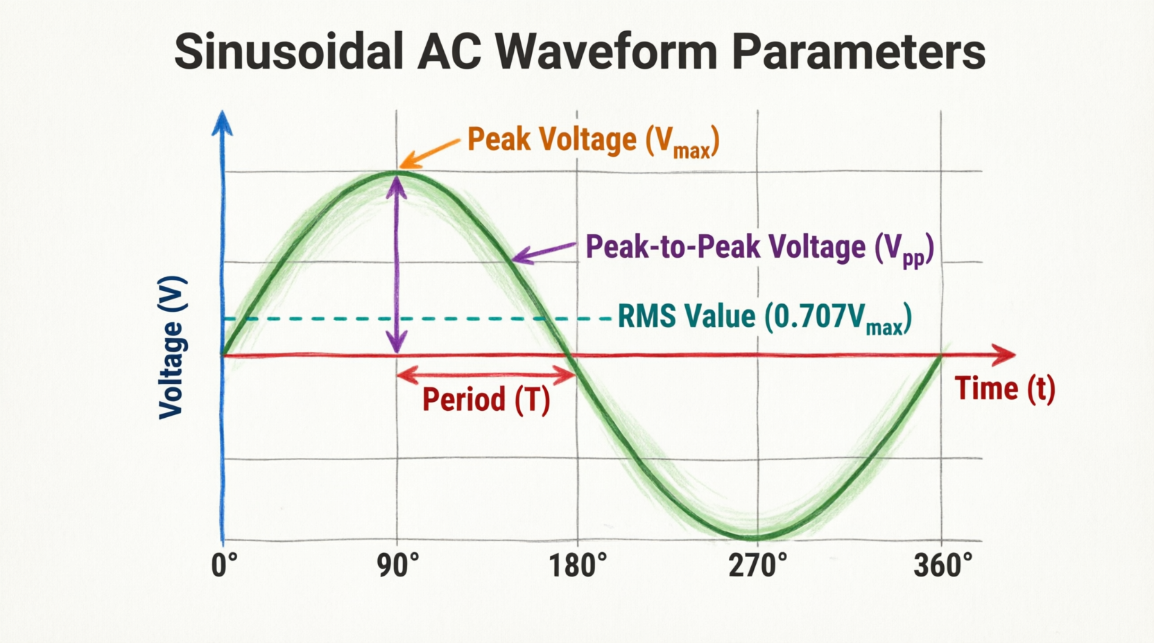
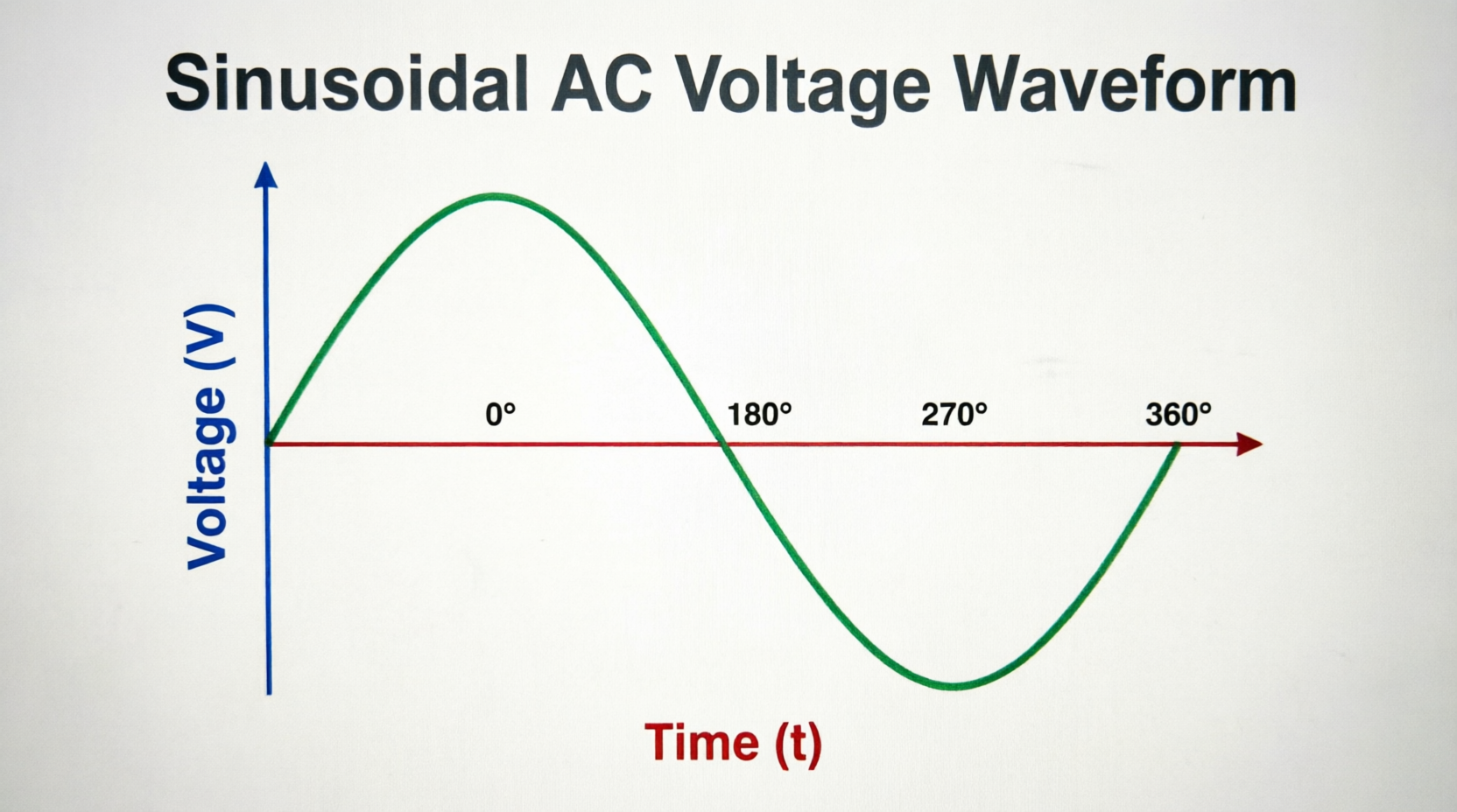
What is AC Waveform? An AC waveform is a graphical representation of alternating current or voltage that varies periodically with time, typically following a sinusoidal pattern. It oscillates between positive and negative values, completing one full cycle in a specific time period determined by its frequency.
Understanding AC Waveforms
What Makes AC Different from DC?
Direct Current (DC) maintains a constant magnitude and flows in a single direction. Batteries and solar cells are common DC sources. In contrast, Alternating Current (AC) changes both magnitude and direction periodically. This periodic variation is what we call a waveform.
The most common AC waveform is the sinusoidal waveform or sine wave, which follows a smooth, periodic oscillation described by trigonometric sine functions. However, AC waveforms can also take other shapes including square waves, triangular waves, and sawtooth waves, each with unique characteristics and applications.
Characteristics of AC Waveforms
Every AC waveform has several key characteristics that define its behavior:
Amplitude represents the maximum value of the waveform, measured from the zero reference line to the peak. This can be expressed as peak value (Vp or Ip) or peak-to-peak value (Vpp or Ipp), which is the total measurement from the negative peak to the positive peak.
Period (T) is the time required to complete one full cycle of the waveform, measured in seconds. One cycle includes all values from zero, through positive maximum, back through zero, to negative maximum, and returning to zero.
Frequency (f) indicates how many complete cycles occur in one second, measured in Hertz (Hz). Frequency and period are inversely related: f = 1/T. Standard power systems operate at 50 Hz (most countries) or 60 Hz (North America and parts of Asia).
Wavelength (λ) represents the physical distance the wave travels during one complete cycle, particularly relevant in transmission line theory and radio frequency applications.
Mathematical Representation of AC Waveforms
The instantaneous value of a sinusoidal AC voltage or current can be expressed mathematically as:
v(t) = Vm × sin(ωt + φ)
Where:
- v(t) = instantaneous voltage at time t
- Vm = maximum or peak voltage
- ω = angular velocity in radians per second (ω = 2πf)
- t = time in seconds
- φ = phase angle in radians or degrees
Similarly, for current:
i(t) = Im × sin(ωt + φ)
This mathematical representation allows engineers to analyze and predict circuit behavior with precision.
What is the Standard AC Frequency? The standard AC frequency for power systems is either 50 Hz or 60 Hz, depending on the region. Most countries use 50 Hz, while North America and parts of Asia use 60 Hz. This means the current changes direction 100 or 120 times per second respectively.
AC Circuit Fundamentals
Basic AC Circuit Components
AC circuits contain various components that respond differently to alternating current:
Resistors (R) oppose current flow and dissipate energy as heat. In AC circuits, resistors behave similarly to DC circuits, with voltage and current remaining in phase.
Inductors (L) store energy in magnetic fields and oppose changes in current. They cause current to lag behind voltage by 90 degrees in purely inductive circuits.
Capacitors (C) store energy in electric fields and oppose changes in voltage. They cause current to lead voltage by 90 degrees in purely capacitive circuits.
Ohm’s Law in AC Circuits
While Ohm’s Law (V = IR) applies to DC circuits, AC circuits require a more comprehensive approach due to the presence of reactance and impedance. In AC circuits:
V = I × Z
Where Z represents impedance, a complex quantity that combines resistance and reactance. This relationship forms the foundation of AC circuit analysis.
Kirchhoff’s Laws for AC Circuits
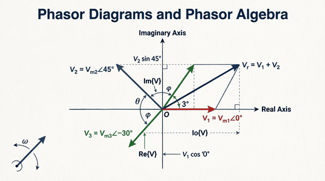
Kirchhoff’s laws remain valid for AC circuits but must be applied using phasor quantities:
Kirchhoff’s Current Law (KCL): The phasor sum of currents entering a node equals the phasor sum of currents leaving the node.
Kirchhoff’s Voltage Law (KVL): The phasor sum of voltages around any closed loop equals zero.
These laws enable systematic analysis of complex AC networks.
RMS Values and Average Values
Understanding RMS (Root Mean Square)
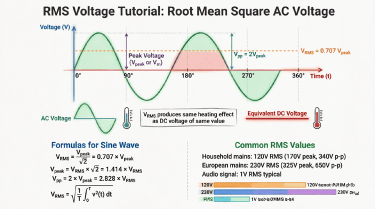
The RMS value is perhaps the most important concept in AC circuit analysis. It represents the equivalent DC value that would produce the same heating effect in a resistive load.
For a sinusoidal waveform:
VRMS = Vm / √2 ≈ 0.707 × Vm
IRMS = Im / √2 ≈ 0.707 × Im
The RMS value is what multimeters measure and what is specified for AC power systems. When we say “120V AC” or “230V AC,” we’re referring to RMS values.
Derivation of RMS Value
The RMS value is calculated by:
- Squaring the instantaneous values over one complete cycle
- Finding the average (mean) of these squared values
- Taking the square root of this average
Mathematically:
VRMS = √(1/T ∫₀ᵀ v²(t) dt)
This mathematical approach ensures that both positive and negative portions of the waveform contribute equally to the heating effect.
Average Value of AC Waveforms
The average value of a complete sinusoidal cycle is zero because the positive and negative halves cancel each other. However, the average value over a half-cycle is useful for certain calculations:
Vavg (half-cycle) = 2Vm/π ≈ 0.637 × Vm
This value is important in rectifier circuits and certain measurement applications.
What is RMS Value? RMS (Root Mean Square) value is the effective value of AC that produces the same heating effect as an equivalent DC value. For sinusoidal waveforms, RMS = Peak Value / √2, or approximately 0.707 times the peak value.
Power in AC Circuits
Instantaneous and Average Power
Power in AC circuits varies continuously throughout the cycle. The instantaneous power is:
p(t) = v(t) × i(t)
For sinusoidal voltage and current:
p(t) = Vm × Im × sin(ωt) × sin(ωt + φ)
The average power over one complete cycle is what matters for practical applications:
P = VRMS × IRMS × cos(φ)
Where cos(φ) is the power factor.
Real, Reactive, and Apparent Power
AC power systems involve three types of power:
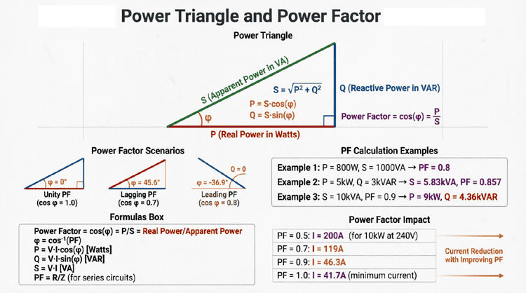
Real Power (P) measured in watts (W), represents actual work performed or energy consumed. This is the useful power that performs mechanical work, generates heat, or produces light.
Reactive Power (Q) measured in volt-amperes reactive (VAR), oscillates between source and load without performing useful work. It’s necessary for establishing magnetic and electric fields in inductive and capacitive components.
Apparent Power (S) measured in volt-amperes (VA), is the product of RMS voltage and current: S = VRMS × IRMS. It represents the total power that must be supplied by the source.
These three powers form the power triangle:
S² = P² + Q²
Power Factor
Power factor is the ratio of real power to apparent power:
Power Factor = P/S = cos(φ)
A power factor of 1 (unity) indicates all power is real power, typical of purely resistive loads. Lower power factors indicate the presence of reactive power, which reduces system efficiency and increases current requirements.
Industrial facilities often install power factor correction capacitors to improve efficiency and reduce electricity costs.
AC Circuit Analysis Techniques
Series AC Circuits
In series AC circuits, components share the same current, but voltages across individual components may differ in magnitude and phase.
For a series R-L-C circuit:
- Total impedance: Z = √(R² + (XL – XC)²)
- Current: I = V/Z
- Phase angle: φ = tan⁻¹((XL – XC)/R)
Where XL = inductive reactance and XC = capacitive reactance.
Parallel AC Circuits
In parallel AC circuits, components share the same voltage, but currents through individual branches differ.
Analysis involves:
- Calculating individual branch currents
- Using phasor addition to find total current
- Determining equivalent impedance
Resonance in AC Circuits
Resonance occurs when inductive and capacitive reactances are equal (XL = XC), resulting in:
- Minimum impedance in series circuits
- Maximum impedance in parallel circuits
- Unity power factor
- Resonant frequency: fr = 1/(2π√LC)
Resonance is crucial in radio tuning, filters, and many electronic applications.
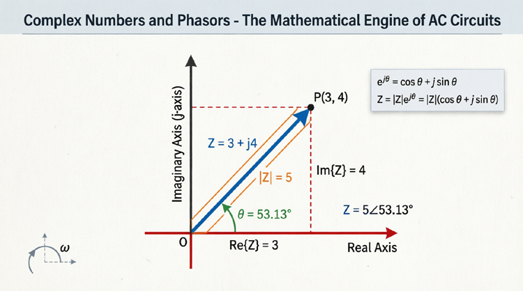
What is Impedance? Impedance (Z) is the total opposition to AC current flow, combining resistance (R) and reactance (X). It’s measured in ohms and represented as Z = R + jX, where j is the imaginary unit. Impedance determines the relationship between AC voltage and current.
Practical Applications
Basic AC Circuit Example
Consider a simple series AC circuit with a resistor and inductor:
Circuit Parameters:
- Supply voltage: 120V RMS, 60Hz
- Resistance: 10Ω
- Inductance: 0.1H
Analysis:
- Calculate inductive reactance: XL = 2πfL = 2π(60)(0.1) = 37.7Ω
- Find impedance: Z = √(10² + 37.7²) = 39.0Ω
- Determine current: I = V/Z = 120/39.0 = 3.08A
- Calculate phase angle: φ = tan⁻¹(37.7/10) = 75.1°
Power Distribution Systems
AC waveform theory is fundamental to understanding electrical power distribution:
Single-Phase Systems: Common in residential applications, using two wires (line and neutral).
Three-Phase Systems: Used in industrial and commercial applications, providing more efficient power transmission with three sinusoidal voltages 120° apart.
Measurement and Instrumentation
Understanding AC waveforms is essential for proper measurement:
Oscilloscopes display waveform shape, amplitude, and frequency.
True RMS Meters accurately measure RMS values regardless of waveform shape.
Power Analyzers measure real, reactive, and apparent power along with power factor.
Common AC Waveform Problems and Solutions
Problem 1: Calculating Peak Value
Question: A standard household outlet provides 120V RMS. What is the peak voltage?
Solution: Vm = VRMS × √2 = 120 × 1.414 = 169.7V
Problem 2: Determining Frequency
Question: An AC waveform completes 300 cycles in 5 seconds. What is the frequency?
Solution: f = cycles/time = 300/5 = 60 Hz
Problem 3: Power Calculation
Question: A circuit draws 10A from a 240V source with a power factor of 0.85. Calculate real power.
Solution: P = V × I × PF = 240 × 10 × 0.85 = 2,040W
Advanced Concepts in AC Theory
Harmonics and Non-Sinusoidal Waveforms
Real-world AC systems often contain harmonics—frequencies that are integer multiples of the fundamental frequency. These arise from non-linear loads like computers, LED lights, and variable speed drives.
Total Harmonic Distortion (THD) quantifies waveform distortion:
THD = √(ΣVn²)/V1 × 100%
Where Vn represents harmonic voltages and V1 is the fundamental.
Transient Response in AC Circuits
When AC circuits are switched on or experience sudden changes, they undergo transient periods before reaching steady-state. This involves exponential decay terms superimposed on sinusoidal steady-state responses.
Three-Phase AC Systems
Three-phase systems use three sinusoidal voltages separated by 120°:
Va = Vm sin(ωt) Vb = Vm sin(ωt – 120°) Vc = Vm sin(ωt – 240°)
Advantages include:
- Constant power transfer
- Efficient motor operation
- Reduced conductor requirements
- Smoother DC conversion