Clipper and Clamper: A Detailed Analysis
The field of signal processing is a vast and intricate domain, often requiring a deep understanding of various components and concepts. Two terms that frequently emerge in the realm of signal processing are “clipper” and “clamper.”
The Basics of Clipper
1. Clipper Definition
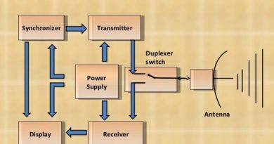
A clipper is essentially a device or circuit designed to restrict the amplitude of an input signal to a predetermined level. Put simply, it curtails the signal’s amplitude above a specified threshold without distorting its original shape. The operation of a clipper is grounded in the principle of electrical or magnetic saturation.
2. Clipper Applications
Clipper circuits find primary utilization in RF (Radio Frequency) transmitters, where their function is critical. They prevent signal amplitude overflow in power amplifiers, a situation that could potentially damage these amplifiers. Additionally, clipper circuits serve as effective tools for noise reduction by eliminating noise components that exceed a predetermined threshold.
Understanding the Clamper
Clamper Unveiled
Conversely, a clamper is a circuit that “clamps” or confines the amplitude of signal voltage within a specified range. It maintains the signal voltage at a predefined level, ensuring it does not surpass a certain threshold.
Clamper Applications
Clamper circuits are frequently deployed in analog circuits for safeguarding against voltage spikes or excessive voltage, both of which could inflict harm upon sensitive electronic components. Moreover, clamper circuits prove beneficial in noise reduction scenarios by clamping off voltage spikes caused by undesirable background noise.
Clipper vs. Clamper:
1. Differences Demystified
While both clipper and clamper serve the common purpose of restraining signal amplitude, there is a fundamental distinction between the two:
- Clipper attenuates signal amplitude above a threshold without altering its shape, often due to nonlinear compression effects. This may lead to signal distortion if amplitude levels exceed the compression point.
- In contrast, clamper restricts voltage amplitude to a specified range by clamping signal voltage at a predefined level. It preserves the signal’s shape but may cause a loss of signal amplitude information if the signal amplitude exceeds the clamping level.
Real-World Applications
Practical Use Cases
Clipper and clamper circuits serve as indispensable components in various applications within the field of signal processing. Here are some specific scenarios where they prove invaluable:
Clipper:
RF Transmitters: Clipper circuits are instrumental in RF transmitters, where they play a crucial role in averting signal amplitude overflow in power amplifiers, thus safeguarding these vital components from damage.
Clamper:
Voltage Protection: In analog circuits, clamper circuits act as guardians, shielding sensitive electronic components from the potential harm caused by voltage spikes or excessive voltage.
Noise Reduction: Beyond voltage protection, clamper circuits contribute to noise reduction efforts by suppressing voltage spikes stemming from unwanted background noise.
Conclusion
In the intricate realm of signal processing, clipper and clamper circuits each serve distinct yet vital roles. The clipper attenuates signal amplitude above a threshold without distorting its shape, while the clamper confines voltage amplitude within a predetermined range without altering the signal’s shape. Understanding these fundamental differences equips professionals in the field of RF transmitters, analog signal processing, and noise reduction systems with the knowledge needed to apply these circuits effectively.
FAQs
1. What are the primary applications in which clipper circuits use?
- Clipper circuits are predominantly used in RF transmitters to prevent signal amplitude overflow in power amplifiers. They also find use in noise reduction by eliminating noise components that exceed a predefined threshold.
2. How do clamper circuits contribute to voltage protection?
- Clamper circuits safeguard sensitive electronic components in analog circuits by clamping off voltage spikes and preventing excessive voltage levels that could potentially damage these components.
3. Can clipper and clamper circuits be used together in a single system?
- Yes, clipper and clamper circuits can be integrated into a single system to address specific signal processing requirements. Their combined functionality can provide enhanced control over signal amplitudes and shapes.
4. Are clipper and clamper circuits solely limited to RF transmitters and analog circuits?
- While these circuits are commonly used in RF transmitters and analog circuits, their applications extend beyond these domains. They can be adapted to suit various signal processing needs, making them versatile tools.
5. How can I further explore the intricacies of signal processing?
- To delve deeper into the world of signal processing, consider seeking educational resources, tutorials, and practical hands-on experience. Exploring academic courses or joining relevant online communities can also be beneficial.