Sinusoidal Waveforms
Sinusoidal Waveforms: The Complete Guide to AC Sine Waves
When we talk about Alternating Current (AC), the first image that comes to mind is almost always a smooth, undulating wave that gracefully rises and falls. This is the sinusoidal waveform, commonly known as a sine wave. It is the fundamental waveform of AC power and serves as the building block for all other periodic signals in electrical engineering.
But why is the sine wave so special? The answer lies in the laws of physics. When a coil of wire rotates uniformly within a magnetic field—as it does in almost all commercial electrical generators—the electromotive force (EMF) induced in the coil naturally takes the shape of a sine wave. Because our global power infrastructure is built on rotating machinery, the sinusoidal waveform is the default shape of the electricity that powers our homes, industries, and devices.
Understanding the anatomy, mathematics, and generation of sinusoidal waveforms is critical for anyone studying electronics, power systems, or telecommunications. This comprehensive guide will break down every aspect of the sine wave, from its basic physical characteristics to the complex mathematical equations that govern its behavior.
What is a Sinusoidal Waveform?
A sinusoidal waveform is a smooth, periodic oscillating curve that mathematically follows the trigonometric sine function. In electrical engineering, it represents the most common form of Alternating Current (AC) voltage and current, characterized by its continuous, symmetrical transition between positive and negative peaks.
Anatomy of a Sine Wave
To fully grasp sinusoidal waveforms, we must first understand the terminology used to describe their physical shape and behavior. A sine wave is not just a random squiggle; it is a highly structured geometric representation of electrical energy over time.
Alternations and Cycles
A sine wave consists of two distinct halves, known as alternations.
- Positive Alternation (Half-Cycle): The portion of the wave that rises above the zero reference line, reaching a positive maximum before returning to zero.
- Negative Alternation (Half-Cycle): The portion of the wave that dips below the zero reference line, reaching a negative minimum before returning to zero.
One complete cycle consists of both the positive and negative alternations combined. It represents one full sequence of values after which the wave begins to repeat itself.
Amplitude: Peak and Peak-to-Peak Values
The height of the wave is referred to as its amplitude. However, amplitude can be measured in a few different ways:
- Instantaneous Value (e or i): The value of the voltage or current at any specific, infinitesimally small point in time.
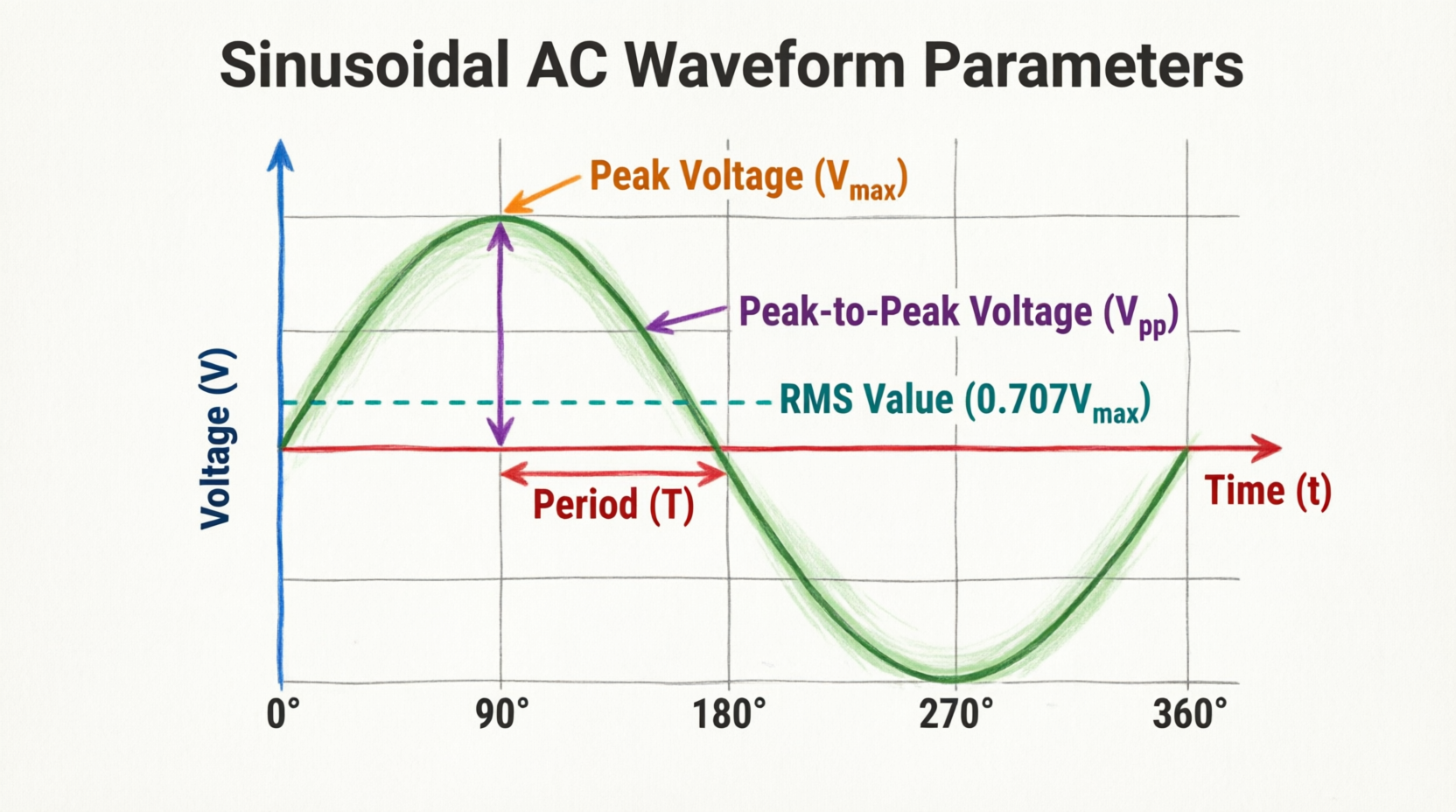
- Peak Value (Vm or Im): Also known as the maximum value or amplitude ($E_{max}$). This is the highest voltage or current reached during either the positive or negative alternation.
- Peak-to-Peak Value (Vpp or Ipp): The total voltage or current difference between the maximum positive peak and the maximum negative peak. For a symmetrical sine wave, $V_{pp} = 2 \times V_m$.
Period, Frequency, and Wavelength
Time and space are crucial to defining a sine wave:
- Period (T): The time it takes for one complete cycle to occur. It is measured in seconds (s), milliseconds (ms), or microseconds (µs).
- Frequency (f): The number of complete cycles that occur in one second. Measured in Hertz (Hz), frequency is the mathematical reciprocal of the period: $f = 1/T$.
- Wavelength (λ): While usually applied to radio waves traveling through space, wavelength is the physical distance a wave travels during one period.
What are the Main Parts of a Sine Wave?
The main parts of a sine wave include the positive and negative alternations (half-cycles), the peak amplitude (maximum value), the peak-to-peak value, the period (time for one cycle), and the zero-crossing points where the wave intersects the horizontal axis.
The Mathematics of Sinusoidal Waveforms
While visual representations are helpful, electrical engineers rely on mathematics to analyze and design AC circuits. The sinusoidal waveform is defined by a precise trigonometric equation.
The General Sine Wave Equation
The instantaneous value of an AC voltage or current at any given angle or time can be calculated using the general sine equation:
v(θ) = Vm × sin(θ)
Where:
- v(θ) is the instantaneous voltage at a specific angle θ.
- Vm is the peak (maximum) voltage.
- sin(θ) is the trigonometric sine of the angle.
Since the angle θ is directly related to time in an AC generator, we can express the equation in terms of time:
v(t) = Vm × sin(ωt)
Where:
- v(t) is the instantaneous voltage at time t.
- ω (omega) is the angular velocity in radians per second.
- t is the time in seconds.
Understanding Angular Velocity (ω)
Angular velocity, or angular frequency, describes how fast the sine wave is oscillating in terms of radians. Since one complete cycle of a sine wave equals $2\pi$ radians (or 360 degrees), and the wave completes f cycles per second, the angular velocity is calculated as:
ω = 2πf
For a standard 60 Hz power system in North America:
ω = 2 × π × 60 ≈ 377 radians per second.
This means the phase angle of the wave advances by 377 radians every single second!
Calculating Instantaneous Values
Let’s look at a practical example to see how this math is applied in the real world.
Example Problem:
An AC voltage source has a peak voltage ($V_m$) of 100V and operates at a frequency of 50 Hz. Calculate the instantaneous voltage at $t = 5$ milliseconds (0.005 seconds).
Step-by-Step Solution:
- Identify the given values: $V_m = 100V$, $f = 50 Hz$, $t = 0.005 s$.
- Calculate angular velocity: $ω = 2πf = 2 × 3.1416 × 50 = 314.16 \text{ rad/s}$.
- Calculate the angle in radians: $θ = ωt = 314.16 × 0.005 = 1.5708 \text{ radians}$.
- Convert to degrees (optional but helpful for visualization): $1.5708 \text{ rad} × (180/π) = 90^\circ$.
- Calculate instantaneous voltage: $v(t) = 100 × \sin(90^\circ) = 100 × 1 = 100V$.
Note: At exactly 90 degrees (or $\pi/2$ radians), the sine wave is at its exact peak, which matches our calculation!
Generating a Sinusoidal Waveform
To truly understand why AC takes the shape of a sine wave, we must look at the physical process of its generation: the AC generator, or alternator.
The Rotating Coil Principle
Imagine a simple loop of wire rotating between the North and South poles of a permanent magnet. According to Faraday’s Law of Electromagnetic Induction, a voltage is induced in the wire whenever it cuts through magnetic flux lines.
As the loop rotates at a constant speed, the angle at which the wire cuts the magnetic field changes continuously:
- At 0°: The wire moves parallel to the magnetic field. It cuts zero flux lines. Induced voltage is zero.
- At 90°: The wire moves perpendicular to the magnetic field. It cuts flux lines at the maximum rate. Induced voltage is at positive maximum (+Vm).
- At 180°: The wire is again moving parallel to the field. Induced voltage drops back to zero.
- At 270°: The wire moves perpendicular again, but in the opposite direction relative to the field. Induced voltage reaches negative maximum (-Vm).
- At 360°: The loop completes one revolution, and the cycle repeats.
Because the rate at which the wire cuts the magnetic field follows a trigonometric sine function based on the angle of rotation, the resulting induced voltage is a perfect sinusoidal waveform.
Visualizing the AC Generator
Diagram Description: The bright blue arrows represent the uniform magnetic field flowing from the North (red) to the South (blue) pole. The golden loop represents the rotating conductor. As it spins, the silver slip rings and grey carbon brushes transfer the generated Bright Red sinusoidal voltage to the external circuit.
Average and RMS Values of a Sine Wave
Because a sinusoidal waveform is constantly changing, we cannot use a single instantaneous value to describe its overall power or effect. Instead, we use standardized mathematical averages.
The Average Value
If you calculate the mathematical average of a complete sine wave cycle, the result is exactly zero. This is because the positive alternation is a perfect mirror image of the negative alternation, and they cancel each other out.
However, in practical applications like rectifier circuits, we often need the average value over just one half-cycle. The average value of a half-wave sine is calculated as:
Vavg = 0.637 × Vm (or $2Vm / \pi$)
The RMS (Root Mean Square) Value
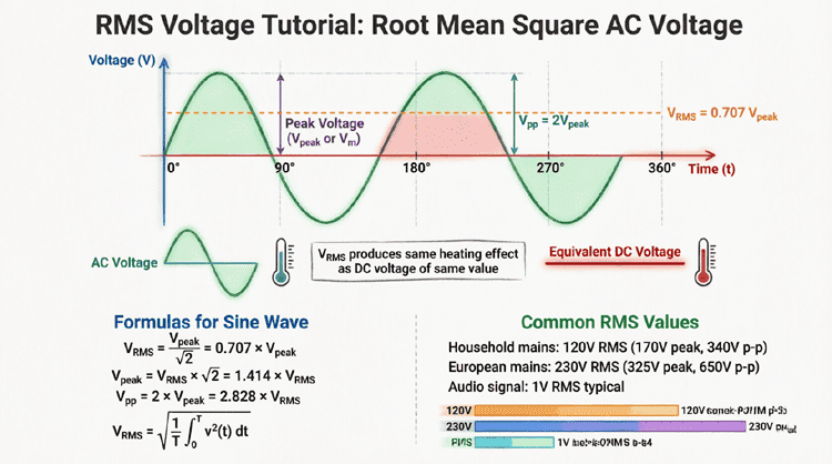
The RMS value is the most important measurement in AC circuits. It represents the “effective” value of the sine wave. Specifically, the RMS value of an AC sine wave is equal to the amount of DC voltage that would produce the exact same amount of heat in a resistive load.
For a pure sinusoidal waveform, the RMS value is calculated as:
VRMS = 0.707 × Vm (or $Vm / \sqrt{2}$)
Conversely, if you know the RMS value (which is what standard multimeters display), you can find the peak value:
Vm = 1.414 × VRMS (or $VRMS \times \sqrt{2}$)
What is the Form Factor of a Sine Wave?
The form factor of a waveform is the ratio of its RMS value to its average value (over a half-cycle). For a pure sinusoidal waveform, the form factor is always approximately 1.11 (0.707 / 0.637).
Visualizing Sinusoidal Waveforms on an Oscilloscope
In the real world, engineers use oscilloscopes to visualize sinusoidal waveforms. An oscilloscope graphs voltage (Y-axis) against time (X-axis), turning electrical signals into visible sine waves.
Setting Up the Measurement
To accurately measure a sine wave on an oscilloscope, you must understand two main controls:
- Volts/Div (Vertical): Determines how many volts each vertical grid square represents. This allows you to measure the peak-to-peak voltage by counting the vertical squares from the top of the wave to the bottom.
- Time/Div (Horizontal): Determines how much time each horizontal grid square represents. This allows you to measure the period of the wave by counting the horizontal squares for one complete cycle.
Measuring Phase Shift
When comparing two sine waves (like voltage and current in an AC circuit), the oscilloscope can reveal the phase difference. If the voltage wave reaches its peak before the current wave, the voltage is said to “lead” the current. The horizontal distance between the zero-crossing points of the two waves, multiplied by the Time/Div setting, gives the time delay, which can be converted into a phase angle in degrees.
Practical Applications and Circuit Responses
Sinusoidal waveforms behave differently depending on the components they encounter in a circuit.
Purely Resistive Circuits
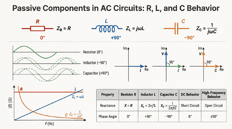
When a sine wave voltage is applied to a purely resistive circuit (like an electric heater), the current waveform perfectly matches the voltage waveform. They rise and fall together, crossing zero at the exact same time. In this scenario, voltage and current are in phase (0° phase difference).
Purely Inductive and Capacitive Circuits
When sine waves interact with inductors (coils) and capacitors, the magic of AC theory truly begins.
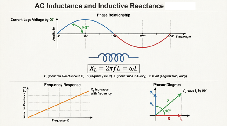
- In a pure inductor, the current waveform lags behind the voltage waveform by exactly 90 degrees (a quarter of a cycle).
- In a pure capacitor, the current waveform leads the voltage waveform by exactly 90 degrees.
This phase shift occurs because inductors oppose changes in current (storing energy in magnetic fields), while capacitors oppose changes in voltage (storing energy in electric fields).
Conclusion
The sinusoidal waveform is the undisputed king of AC electricity. From its physical generation via rotating magnetic fields to its mathematical representation using trigonometric functions, the sine wave dictates how power is transmitted, distributed, and consumed across the globe.
Key takeaways from this guide include:
- A sine wave consists of positive and negative alternations forming complete cycles.
- The mathematical equation $v(t) = V_m \sin(\omega t)$ defines the instantaneous value at any given time.
- Angular velocity ($\omega = 2\pi f$) connects the frequency of the wave to its rotational speed in radians.
- The RMS value (0.707 × Peak) is the standard measurement for AC power because it equates to equivalent DC heating effects.
- Oscilloscopes allow engineers to visually analyze the amplitude, frequency, and phase shifts of sine waves in real-time.
Mastering the concepts of sinusoidal waveforms provides the essential foundation for all subsequent studies in AC circuit theory, including phasor diagrams, impedance, and complex power calculations. Whether you are designing a simple audio amplifier or analyzing a multi-megawatt power grid, the sine wave remains the fundamental language of alternating current.