Phase Difference and Phase Shift
Phase Difference and Phase Shift: The Ultimate Guide to AC Timing
In Direct Current (DC) circuits, analyzing voltage and current is relatively straightforward. You apply a voltage, and a current flows. They happen simultaneously, and their relationship is governed simply by Ohm’s Law. However, when we transition to Alternating Current (AC), the story becomes much more dynamic. Because AC voltage and current are constantly changing in magnitude and direction, when they reach their peaks and zero-crossings becomes just as important as how high those peaks are.
This concept of “timing” in AC circuits is known as phase. When two AC waveforms of the same frequency do not reach their maximum and minimum points at the exact same time, we say there is a phase difference or phase shift between them.
Understanding phase shift is arguably the most critical hurdle in mastering AC circuit theory. It dictates how power is consumed, how motors spin, and how electrical grids remain stable. This comprehensive guide will demystify phase difference, exploring its mathematical representation, its physical causes in basic components, and how to measure it in the real world.
What is Phase Difference?
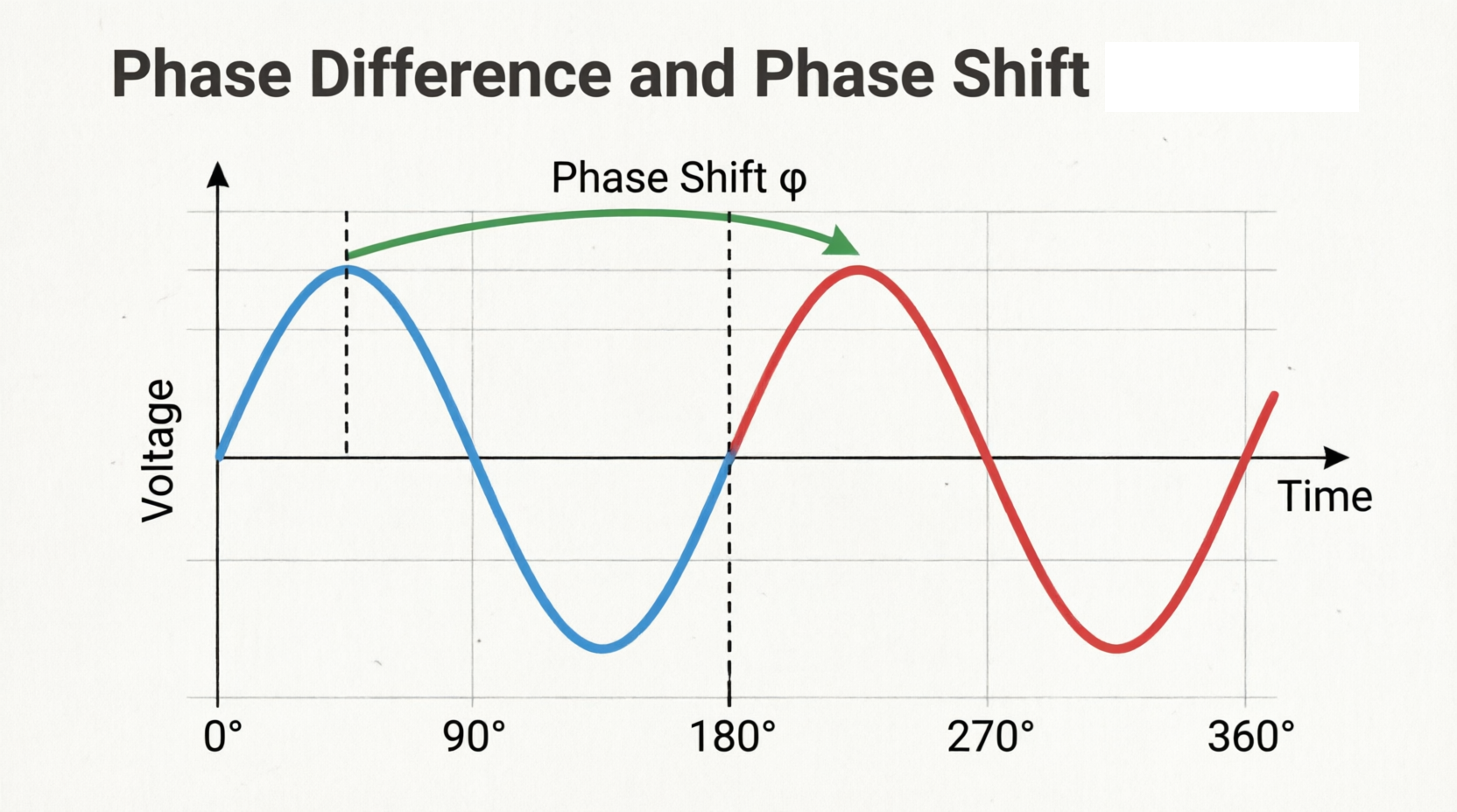
Phase difference (or phase shift) is the angular difference in degrees or radians between two AC waveforms of the same frequency. It occurs when one waveform reaches its peak (or zero-crossing) before the other, meaning the waves are “out of sync” with each other.
Understanding Phase and Phase Angle
Before we can understand phase difference, we must first understand what a phase is on its own.
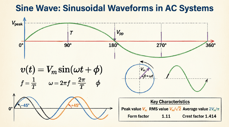
In the context of a sine wave, “phase” refers to the instantaneous position of the waveform within its cycle at a specific moment in time. It is usually expressed as an angle (in degrees or radians) because a complete cycle of a sine wave corresponds to one full rotation (360° or $2\pi$ radians) of the AC generator.
The Reference Waveform
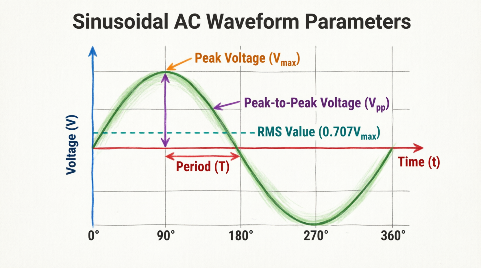
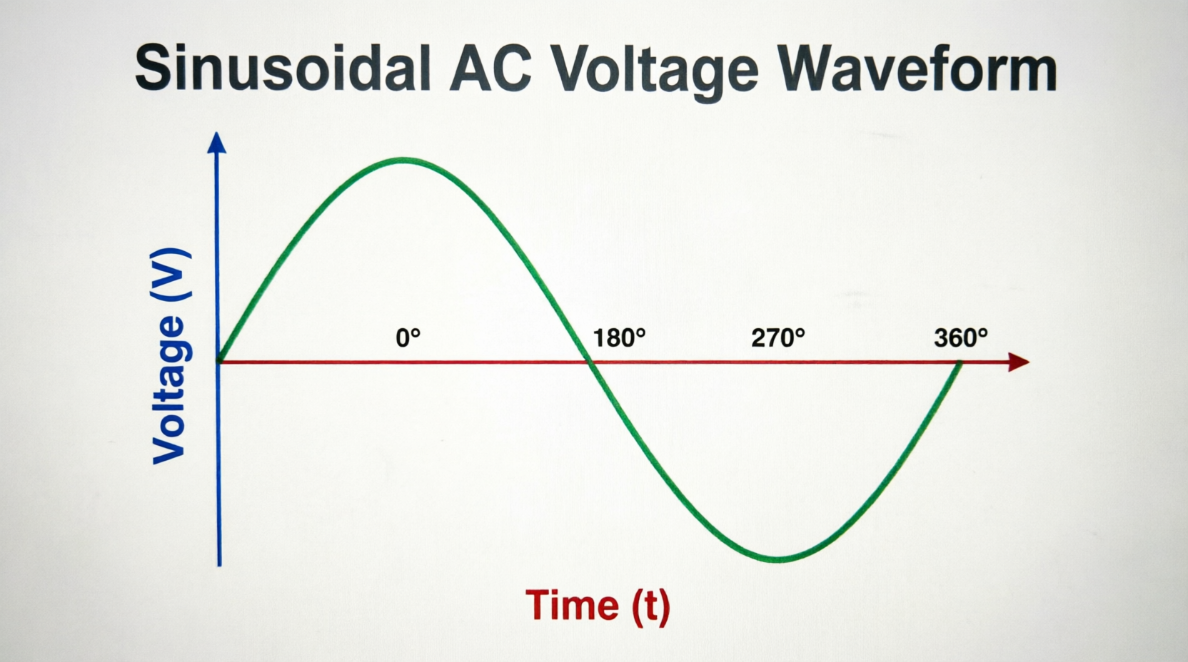
To measure phase, we need a starting point, known as the reference waveform. By convention, the horizontal axis (the zero line) where the wave begins its positive alternation is defined as 0° phase.
- At 90°, the wave is at its positive peak.
- At 180°, it crosses zero again.
- At 270°, it is at its negative peak.
- At 360°, it completes the cycle and returns to 0°.
When we have two waveforms, we designate one as the reference (0°) and measure the position of the second waveform relative to the first. This relative measurement is the phase angle ($\phi$).
What is Phase Shift? Lead vs. Lag
When two sine waves have a phase difference, one wave will always reach a specific point in its cycle before the other. This creates two distinct conditions: Leading and Lagging.
Leading Phase
If Waveform A reaches its positive peak before Waveform B (the reference), Waveform A is said to lead Waveform B. Imagine two runners on a circular track running at the exact same speed, but Runner A started a few seconds before Runner B. Runner A is always ahead, or “leading.”
Lagging Phase
Conversely, if Waveform B reaches its positive peak after Waveform A, Waveform B is said to lag Waveform A. In our runner analogy, Runner B is “lagging” behind.
What is the Difference Between Leading and Lagging?
A leading waveform reaches its peak earlier in time than the reference waveform, while a lagging waveform reaches its peak later. In AC circuits, if current leads voltage, the load is capacitive; if current lags voltage, the load is inductive.
Mathematical Representation of Phase Shift
To analyze phase shift mathematically, we incorporate a phase angle ($\phi$) into the standard sine wave equation.
If we have a reference voltage wave and a current wave that is shifted by an angle $\phi$, their equations look like this:
Reference Voltage: $v(t) = V_m \sin(\omega t)$
Shifted Current: $i(t) = I_m \sin(\omega t \pm \phi)$
- The $+$ sign indicates that the current leads the voltage. The wave is shifted to the left on a time-domain graph.
- The $-$ sign indicates that the current lags the voltage. The wave is shifted to the right on a time-domain graph.
Visualizing Phase Shift in the Time Domain
Diagram Description: The Neon Red sine wave represents the reference voltage. The Electric Blue sine wave represents the current. Notice how the blue wave reaches its peak later than the red wave. The horizontal distance between their peaks is the time delay ($\Delta t$), which translates to the phase shift angle ($\phi$). Here, the current lags the voltage.
Phase Relationships in Basic AC Components
The most fascinating aspect of phase shift is how it is dictated by the physical components in a circuit. Resistors, inductors, and capacitors interact with AC voltage and current in fundamentally different ways.
1. The Pure Resistor: In-Phase (0° Shift)
In a purely resistive AC circuit (like a standard incandescent lightbulb or a heating element), the voltage and current are perfectly synchronized. When the voltage pushes, the current flows instantly. When the voltage drops to zero, the current drops to zero simultaneously.
- Phase Angle ($\phi$): 0°
- Relationship: Voltage and Current are in-phase.
2. The Pure Inductor: Current Lags Voltage (90° Shift)
Inductors are coils of wire that store energy in a magnetic field. According to Lenz’s Law, an inductor opposes any change in current by inducing a back-electromotive force (back-EMF).
Because of this opposition, the current cannot build up instantly when voltage is applied. The voltage reaches its maximum first, and the current takes time to “catch up,” reaching its maximum a quarter-cycle (90°) later.
- Phase Angle ($\phi$): 90°
- Relationship: Current lags Voltage by 90°. (Or, Voltage leads Current by 90°).
3. The Pure Capacitor: Current Leads Voltage (90° Shift)
Capacitors store energy in an electric field between two conductive plates. When an AC voltage is first applied, the capacitor is uncharged, so current flows freely to deposit electrons on the plates. As the plates charge up, they create a voltage that opposes the source voltage, slowing the current down.
By the time the capacitor is fully charged (voltage is at its peak), the current has stopped flowing (current is at zero). Therefore, the current reaches its peak before the voltage does.
- Phase Angle ($\phi$): 90°
- Relationship: Current leads Voltage by 90°. (Or, Voltage lags Current by 90°).
The Golden Mnemonic: “ELI the ICE dog”
To remember these relationships, electrical engineering students worldwide use a famous mnemonic: ELI the ICE dog.
- E stands for Electromotive force (Voltage).
- I stands for Current.
- L stands for Inductor.
- C stands for Capacitor.
ELI: In an L (Inductor) circuit, E (Voltage) comes before I (Current). Therefore, Voltage leads Current (Current lags).
ICE: In a C (Capacitor) circuit, I (Current) comes before E (Voltage). Therefore, Current leads Voltage.
What is ELI the ICE dog?
“ELI the ICE dog” is a popular mnemonic used to remember AC phase relationships. In an Inductor (L), Voltage (E) leads Current (I). In a Capacitor (C), Current (I) leads Voltage (E).
Visualizing Phase Shift in the Phasor Domain
While time-domain graphs (oscilloscope views) are excellent for visualizing phase shift over time, they become incredibly cluttered when dealing with complex circuits containing multiple components. To simplify analysis, engineers use Phasor Diagrams.
A phasor is a rotating vector that represents the magnitude (usually RMS) and phase angle of a sinusoidal waveform. Instead of drawing wavy lines, we draw straight arrows originating from a central point.
Constructing a Phasor Diagram
Let’s visualize a circuit where voltage is the reference, and current lags by 60° (an inductive circuit).
Diagram Description: The glowing Magenta arrow represents the Voltage phasor, pointing straight right along the 0° reference axis. The glowing Cyan arrow represents the Current phasor. Because the current lags the voltage by 60°, the Cyan arrow is rotated 60 degrees clockwise from the Magenta arrow. The angle between them is the phase shift ($\phi$).
Measuring Phase Difference in the Real World
In a laboratory or field setting, you cannot simply “look” at a wire and see the phase angle. You must measure it using specialized equipment, primarily the oscilloscope. There are two primary methods for measuring phase shift.
Method 1: The Time-Delay Method (Dual-Trace Oscilloscope)
This is the most common and intuitive method. You connect Channel 1 to measure voltage and Channel 2 to measure current (often using a current clamp or a shunt resistor).
Step-by-Step Measurement:
- Display both waves: Adjust the Volts/Div and Time/Div knobs so both waves are clearly visible and span a few horizontal divisions.
- Measure the Period (T): Count the number of horizontal divisions for one complete cycle of the reference wave (e.g., Voltage). Multiply by the Time/Div setting to get the total period $T$.
- Measure the Time Delay ($\Delta t$): Count the number of horizontal divisions between the zero-crossing points (or peak points) of the two waves. Multiply by the Time/Div setting to get the time delay $\Delta t$.
- Calculate the Phase Angle: Use the following formula:
Phase Angle ($\phi$) = ($\Delta t$ / $T$) × 360°
Example: If one full cycle takes 4 divisions (T = 4 divs), and the waves are shifted by 1 division ($\Delta t$ = 1 div), the phase shift is (1 / 4) × 360° = 90°.
Method 2: The Lissajous Pattern Method (X-Y Mode)
If you don’t know the exact frequency of the signals, or if you want a highly precise measurement, you can use the Lissajous method. This requires switching the oscilloscope to X-Y mode.
In X-Y mode, the oscilloscope stops sweeping the beam horizontally over time. Instead, Channel 1 (Voltage) drives the horizontal X-axis, and Channel 2 (Current) drives the vertical Y-axis. The resulting shape on the screen is called a Lissajous figure.
- If the phase shift is 0° or 180°, the pattern will be a straight diagonal line.
- If the phase shift is exactly 90°, and amplitudes are equal, the pattern will be a perfect circle (or an ellipse if amplitudes differ).
- For any other angle, the pattern will be an ellipse.
To calculate the phase angle from the ellipse, you measure the Y-intercept ($Y_0$) and the maximum Y-deflection ($Y_{max}$):
$\sin(\phi) = Y_0 / Y_{max}$
$\phi = \arcsin(Y_0 / Y_{max})$
This method is incredibly accurate and was the standard way to measure phase before digital oscilloscopes with built-in math functions became common.
The Impact of Phase Shift on Power
Why do we care so much about phase shift? The ultimate answer lies in power.
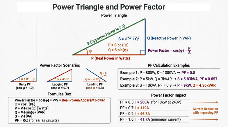
In DC circuits, power is simply Voltage × Current ($P = V \times I$). In AC circuits, because voltage and current are not always peaking at the same time, the actual power consumed is reduced. The formula for real (true) power in an AC circuit is:
$P = V_{RMS} \times I_{RMS} \times \cos(\phi)$
The term $\cos(\phi)$ is known as the Power Factor.
- If voltage and current are in-phase (pure resistor), $\phi = 0°$, and $\cos(0°) = 1$. All the power supplied is real power.
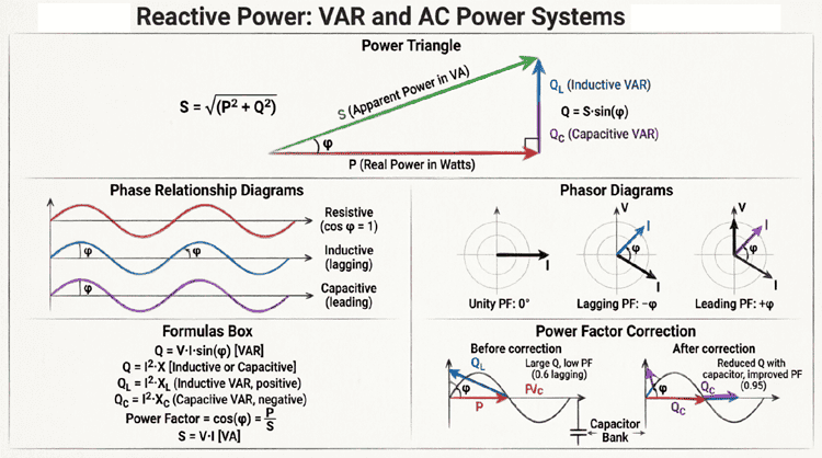
- If the phase shift is 90° (pure inductor or capacitor), $\cos(90°) = 0$. The real power consumed is zero! The energy simply sloshes back and forth between the source and the component, doing no useful work. This is called reactive power.
In industrial settings, large motors (which are highly inductive) cause the current to lag the voltage significantly, resulting in a low power factor. Utility companies penalize factories for low power factors because they must supply higher currents to deliver the same amount of real power, causing unnecessary heat loss in the transmission lines. To fix this, engineers install capacitor banks to introduce a leading phase shift, which cancels out the lagging phase shift of the motors, bringing the overall phase angle back close to 0° and the power factor close to 1.
Practical Examples and Calculations
Let’s solidify these concepts with a few practical calculation examples.
Example 1: Calculating Phase Shift from Time Measurements
Problem: An oscilloscope is set to a Time/Div of 2 ms. A voltage wave and a current wave are displayed. The voltage wave completes one full cycle in 5 divisions. The current wave’s positive peak occurs 1.5 divisions after the voltage wave’s positive peak. Calculate the phase shift and state whether the current leads or lags.
Solution:
- Calculate Period (T): 5 divisions × 2 ms/div = 10 ms.
- Calculate Time Delay ($\Delta t$): 1.5 divisions × 2 ms/div = 3 ms.
- Calculate Phase Angle: $\phi = (3 \text{ ms} / 10 \text{ ms}) \times 360° = 0.3 \times 360° = 108°$.
- Determine Lead/Lag: Since the current peak occurs after (to the right of) the voltage peak, the current lags the voltage by 108°.
Example 2: Writing the Instantaneous Equation
Problem: An AC current has an RMS value of 10A, a frequency of 60 Hz, and leads the reference voltage by 30°. Write the mathematical equation for this current.
Solution:
- Find Peak Current ($I_m$): $I_m = I_{RMS} \times \sqrt{2} = 10 \times 1.414 = 14.14 \text{ A}$.
- Find Angular Velocity ($\omega$): $\omega = 2\pi f = 2 \times 3.1416 \times 60 = 377 \text{ rad/s}$.
- Determine Phase Sign: Since it leads, we use the positive (+) sign for the phase angle.
- Write Equation: $i(t) = 14.14 \sin(377t + 30°)$.
Conclusion
Phase difference and phase shift are the fundamental concepts that separate simple DC theory from the rich, dynamic world of AC circuit analysis. While DC only asks “how much,” AC asks “how much” and “when.”
By understanding how resistors, inductors, and capacitors shift the timing of voltage and current, you unlock the ability to analyze complex AC networks, design filters, tune radio receivers, and optimize industrial power systems. The transition from time-domain waveforms to phasor diagrams provides a powerful mathematical toolkit, turning complex trigonometric calculus into simple vector geometry.
Whether you are using the “ELI the ICE dog” mnemonic to pass an exam, measuring time delays on an oscilloscope in a lab, or calculating power factor corrections for a manufacturing plant, the principles of phase shift remain at the very heart of electrical engineering. Mastering this concept is not just an academic exercise; it is the key to understanding how the modern, electrified world truly operates.