AC Resistance and Impedance
AC Resistance and Impedance: The Complete Guide to AC Opposition
The Evolution of “Opposition” in AC Circuits
When you first learn about Direct Current (DC) circuits, the concept of opposition to current flow is beautifully simple. You have Resistance ($R$), measured in Ohms ($\Omega$), which acts like friction in a pipe, resisting the flow of electrons and dissipating energy as heat. Ohm’s Law ($V = I \times R$) is all you need to rule the DC world.
However, when we transition to Alternating Current (AC), the simple concept of resistance is no longer enough. Because AC voltage and current are constantly changing direction and magnitude, circuit components react dynamically to these changes. Inductors and capacitors, which act like open or short circuits in DC, suddenly begin to oppose the flow of AC current in entirely new ways.
To analyze AC circuits, we must expand our vocabulary. We introduce Reactance ($X$), the opposition caused by energy storage in magnetic and electric fields, and Impedance ($Z$), the grand unifier that combines both resistance and reactance into a single, comprehensive measurement. This guide will break down the physical meaning, mathematical representation, and real-world applications of AC resistance and impedance.
What is the difference between Resistance and Impedance?
Resistance (R) is the opposition to current flow that dissipates energy as heat, present in both AC and DC circuits. Impedance (Z) is the total opposition to AC current flow, combining both Resistance (R) and Reactance (X). While resistance is a simple scalar value, impedance is a complex vector that includes both magnitude and phase angle.
AC Resistance: Friction in the Electrical Pipe
In an AC circuit, a pure resistor behaves very much like it does in a DC circuit. When an AC voltage is applied across a resistor, the current flowing through it is directly proportional to the voltage at every single instant in time.
The Phase Relationship in Pure Resistance
Because the resistor does not store energy in magnetic or electric fields, it cannot cause a time delay between the voltage and the current. Therefore, in a purely resistive AC circuit, the voltage and current are perfectly in-phase (0° phase shift). They reach their zero-crossings and peak values at the exact same moment.
Visualizing a Purely Resistive AC Circuit
Diagram Description: The Neon Red AC source drives a Crimson Red resistor. Because it is a pure resistor, the Electric Blue current wave is perfectly synchronized (in-phase) with the voltage wave. All electrical energy is converted directly into heat.
Power Dissipation in Resistors
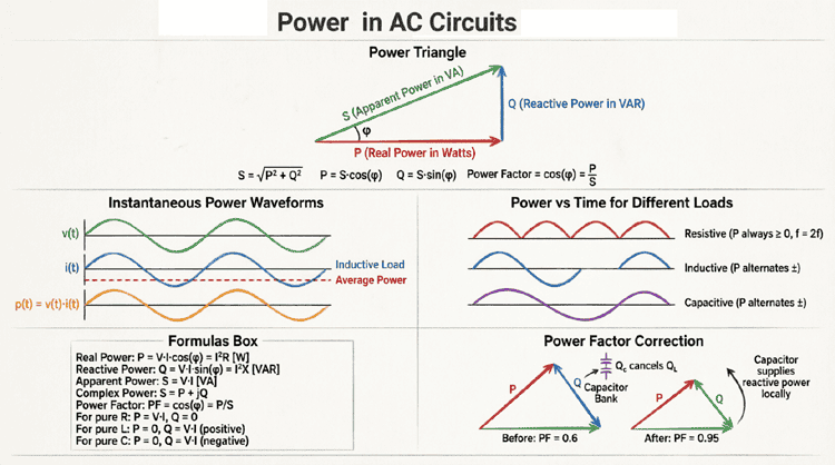
In a resistor, all the power delivered by the AC source is Real Power ($P$), measured in Watts. The formula is identical to DC: $P = I_{RMS}^2 \times R$ or $P = V_{RMS} \times I_{RMS}$. The resistor does not return any energy to the source; it consumes it entirely.
The Skin Effect: Why AC Resistance is Higher than DC Resistance
There is one crucial caveat to AC resistance: at higher frequencies, the effective resistance of a wire increases. This is due to the Skin Effect.
As AC current flows through a conductor, the changing magnetic field inside the wire induces eddy currents that oppose the main current flow. These eddy currents are strongest at the center of the conductor, effectively pushing the main current flow toward the outer “skin” of the wire. Because the effective cross-sectional area of the wire is reduced, the AC resistance ($R_{AC}$) becomes higher than the DC resistance ($R_{DC}$).
To combat the skin effect in high-frequency applications (like radio transmitters or large power grid busbars), engineers use hollow copper tubes or Litz wire (wire made of many individually insulated thin strands) to maximize the surface area available for current flow.
AC Reactance: The Opposition of Energy Storage
While resistors oppose current by dissipating energy, Reactance ($X$) opposes current by temporarily storing energy in magnetic or electric fields and then returning it to the circuit. Reactance is measured in Ohms ($\Omega$), just like resistance, but it causes a 90° phase shift between voltage and current. There are two types of reactance: Inductive and Capacitive.
Inductive Reactance ($X_L$)
Inductors (coils of wire) oppose changes in current. When AC current tries to reverse direction, the inductor’s collapsing magnetic field induces a voltage that fights the change (Lenz’s Law). This opposition is called Inductive Reactance.
The formula for inductive reactance is:
$X_L = 2 \pi f L$
(Where $f$ is frequency in Hz, and $L$ is inductance in Henrys).
Key Characteristic: Inductive reactance is directly proportional to frequency. If you double the frequency of the AC source, the inductor’s opposition to current doubles. In a pure inductor, current lags voltage by 90°.
Capacitive Reactance ($X_C$)
Capacitors oppose changes in voltage. When an AC voltage is applied, the capacitor plates charge up, creating an electric field that pushes back against the source voltage. This opposition is called Capacitive Reactance.
The formula for capacitive reactance is:
$X_C = \frac{1}{2 \pi f C}$
(Where $f$ is frequency in Hz, and $C$ is capacitance in Farads).
Key Characteristic: Capacitive reactance is inversely proportional to frequency. If you double the frequency, the capacitor’s opposition to current is cut in half. In a pure capacitor, current leads voltage by 90°.
How does frequency affect Reactance?
Inductive reactance ($X_L$) increases as frequency increases, acting like a high-frequency block. Capacitive reactance ($X_C$) decreases as frequency increases, acting like a high-frequency pass. This frequency-dependent behavior is the foundational principle behind electronic filters and audio crossovers.
Impedance ($Z$): The Total Opposition to AC
In the real world, circuits rarely contain just pure resistors or pure inductors. A real-world motor, for example, has the resistance of its copper windings and the inductance of its magnetic coils. To calculate the total opposition to current in a mixed AC circuit, we use Impedance ($Z$).
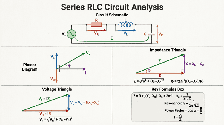
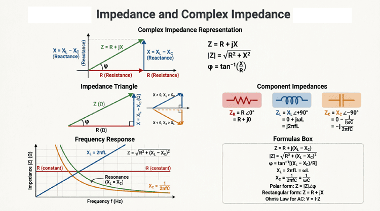
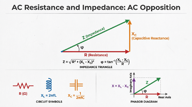
Impedance is a complex quantity that combines Resistance ($R$) and Reactance ($X$) using vector addition, because $R$ and $X$ are 90 degrees out of phase with each other. You cannot simply add them together using standard arithmetic ($Z \neq R + X$). You must use the Pythagorean theorem.
The Impedance Triangle
The relationship between Resistance, Reactance, and Impedance is beautifully visualized using the Impedance Triangle.
Diagram Description: The Crimson Red horizontal vector represents pure Resistance ($R$). The Electric Blue vertical vector represents Net Reactance ($X$). The Golden diagonal vector represents Total Impedance ($Z$). The angle $\theta$ between $R$ and $Z$ is the circuit’s phase angle, determining the power factor.
Calculating Impedance
The magnitude of total impedance is calculated as:
$Z = \sqrt{R^2 + X^2}$
Where $X$ is the net reactance ($X = X_L – X_C$).
The phase angle ($\theta$) of the impedance, which tells us how much the total current lags or leads the voltage, is calculated as:
$\theta = \arctan\left(\frac{X}{R}\right)$
In complex number notation (as learned in the previous article), impedance is written as:
$Z = R + jX$ (Rectangular Form)
$Z = |Z| \angle \theta$ (Polar Form)
Step-by-Step Practical Example: Series RLC Circuit
Let’s apply these concepts to a realistic AC circuit problem.
Problem Statement:
A series circuit is connected to a 120V (RMS), 60Hz AC source. The circuit contains:
- A Resistor: $R = 30 \Omega$
- An Inductor: $L = 0.159 \text{ H}$
- A Capacitor: $C = 53 \mu \text{F}$ ($0.000053 \text{ F}$)
Calculate the inductive reactance, capacitive reactance, total impedance, and the total current flowing through the circuit.
Step 1: Calculate Inductive Reactance ($X_L$)
$X_L = 2 \pi f L$
$X_L = 2 \times 3.1416 \times 60 \times 0.159$
$X_L \approx 60 \Omega$
Step 2: Calculate Capacitive Reactance ($X_C$)
$X_C = \frac{1}{2 \pi f C}$
$X_C = \frac{1}{2 \times 3.1416 \times 60 \times 0.000053}$
$X_C \approx 50 \Omega$
Step 3: Calculate Net Reactance ($X$)
Because $X_L$ and $X_C$ are 180 degrees out of phase with each other (one points up on the complex plane, the other points down), they subtract.
$X = X_L – X_C = 60 – 50 = \mathbf{10 \Omega}$ (Net inductive)
Step 4: Calculate Total Impedance ($Z$)
$Z = \sqrt{R^2 + X^2}$
$Z = \sqrt{30^2 + 10^2}$
$Z = \sqrt{900 + 100} = \sqrt{1000}$
$Z \approx 31.62 \Omega$
Step 5: Calculate Total Current ($I$)
Using the AC version of Ohm’s Law ($I = V / Z$):
$I = \frac{120\text{V}}{31.62\Omega}$
$I \approx 3.79 \text{ Amps}$
Step 6: Calculate Phase Angle ($\theta$)
$\theta = \arctan\left(\frac{X}{R}\right) = \arctan\left(\frac{10}{30}\right) = \arctan(0.333)$
$\theta \approx 18.4^\circ$
Because the net reactance is positive (inductive), the current lags the voltage by 18.4 degrees.
Real-World Applications of Impedance
Understanding impedance is not just about passing exams; it is critical for designing and troubleshooting real-world electrical and electronic systems.
1. Impedance Matching in Audio and RF
In audio engineering and radio frequency (RF) design, Impedance Matching is a vital concept. The Maximum Power Transfer Theorem states that to get the maximum possible power from a source to a load, the load impedance must exactly equal the source impedance (e.g., an 8-ohm speaker connected to an amplifier designed for an 8-ohm load). If the impedances are mismatched, power is reflected back to the source, causing inefficiency, signal distortion, or even equipment damage in RF transmitters.
2. Power Factor Correction in Industry
In industrial manufacturing, large AC motors act as massive inductors, causing the current to lag the voltage significantly. This creates a low Power Factor, meaning the factory is drawing more current from the grid than is actually being used to do useful work. Utility companies charge heavy penalties for this. Engineers fix this by adding capacitors in parallel with the motors. The capacitive reactance ($-jX_C$) cancels out the inductive reactance ($+jX_L$), bringing the total impedance angle closer to zero, correcting the power factor, and saving thousands of dollars in electricity bills.
3. Measuring Impedance: The LCR Meter
How do technicians measure impedance in the field? They use an LCR Meter. Unlike a standard multimeter that only measures DC resistance, an LCR meter applies an AC voltage at a specific test frequency (usually 100 Hz, 1 kHz, or 10 kHz) to the component. By measuring the resulting AC current and the phase shift between the voltage and current, the microprocessor inside the LCR meter calculates and displays the exact Resistance ($R$), Inductance ($L$), Capacitance ($C$), and overall Impedance ($Z$) of the component.
The transition from DC resistance to AC impedance is the gateway to mastering alternating current theory. While resistance is a simple, scalar opposition that dissipates energy as heat, impedance is a complex, vector quantity that accounts for the dynamic energy storage of inductors and capacitors.
Key takeaways from this guide include:
- Resistance ($R$) opposes current in both AC and DC, keeping voltage and current in-phase. The skin effect causes AC resistance to increase at higher frequencies.
- Reactance ($X$) is the opposition caused by inductors ($X_L$) and capacitors ($X_C$). It is highly dependent on the frequency of the AC source.
- Impedance ($Z$) is the total AC opposition, calculated using vector addition ($Z = \sqrt{R^2 + X^2}$) because resistance and reactance are 90 degrees out of phase.
- Impedance Matching is crucial for maximizing power transfer in audio and RF systems, while Power Factor Correction uses capacitive impedance to cancel out inductive impedance in industrial power grids.
By mastering the concepts of resistance and impedance, you now possess the mathematical and physical tools to analyze any linear AC circuit. You understand how components interact, how frequency changes circuit behavior, and how to calculate the exact current flow in complex RLC networks.
In the final article of this series, we will take a deep, focused dive into one of the most fascinating and powerful components in electrical engineering: the inductor. We will explore the profound depths of AC Inductance and Inductive Reactance, uncovering how magnetic fields shape the modern world.