AC Inductance and Inductive Reactance
AC Inductance and Inductive Reactance: The Ultimate Guide to Magnetic Opposition
The Magic of Electromagnetism in AC Circuits
Throughout this comprehensive series on AC circuit theory, we have journeyed from the basic anatomy of a sine wave to the complex mathematics of phasor algebra. Now, we arrive at one of the most fascinating and physically dynamic components in all of electrical engineering: the inductor.
While resistors simply burn energy as heat and capacitors store energy in an electric field, inductors interact with the very fabric of electromagnetism. They store energy in a magnetic field. In a Direct Current (DC) circuit, once the current stabilizes, an inductor essentially becomes a simple piece of wire. But in an Alternating Current (AC) circuit, where the current is perpetually changing direction and magnitude, the inductor becomes a powerful, active participant. It fights against the changes in current, creating a unique form of opposition known as inductive reactance.
Understanding AC inductance is crucial for designing everything from power grids and electric motors to radio receivers and smartphone chargers. This final guide will dissect the physics of inductance, explore the mathematics of inductive reactance, and reveal how magnetic fields shape the modern electrical world.
What is Inductive Reactance?
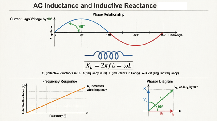
Inductive reactance ($X_L$) is the specific opposition that an inductor presents to the flow of Alternating Current (AC). Unlike standard resistance, inductive reactance does not dissipate energy as heat; instead, it temporarily stores energy in a magnetic field. It is measured in Ohms ($\Omega$) and increases as either the frequency of the AC signal or the physical inductance of the coil increases.
The Physics of Inductance: Self-Induction and Lenz’s Law
To understand how an inductor behaves in an AC circuit, we must first understand the physical principles that govern it. Inductance is rooted in two fundamental laws of physics discovered in the 19th century: Faraday’s Law of Electromagnetic Induction and Lenz’s Law.
Faraday’s Law and the Magnetic Field
When electric current flows through a conductor, it generates a magnetic field around it. If you coil that wire into a loop or a solenoid, the magnetic fields of the individual loops combine, creating a much stronger, concentrated magnetic field through the center of the coil.
Faraday’s Law states that any change in this magnetic field will induce a voltage (Electromotive Force, or EMF) in the conductor. When the AC current increases, the magnetic field expands. When the AC current decreases, the magnetic field collapses. This continuous expansion and collapse induces a voltage within the coil itself—a phenomenon known as self-induction.
Lenz’s Law: The Ultimate Opposer
Lenz’s Law provides the direction of this induced voltage. It states that the induced EMF will always act in a direction that opposes the change in current that created it.
Imagine trying to push a heavy shopping cart. When you first push, it resists your forward motion (inertia). When you try to stop it, it resists your stopping force, wanting to keep rolling. An inductor is the electrical equivalent of mass/inertia. It resists changes in current. If the AC current tries to increase, the inductor induces a back-EMF that pushes back, slowing the rise. If the current tries to decrease, the inductor induces a forward-EMF to keep the current flowing.
Why does an inductor oppose AC current?
An inductor opposes AC current because of self-induction and Lenz’s Law. Since AC current is constantly changing, the inductor’s magnetic field is constantly expanding and collapsing. This changing magnetic field induces a “back-EMF” voltage that always acts in a direction to oppose the change in the AC current flow.
Inductive Reactance ($X_L$): The Mathematical Opposition
In a DC circuit, once the current reaches a steady state, the magnetic field stops changing, the back-EMF drops to zero, and the inductor acts like a short circuit (limited only by the tiny physical resistance of the wire).
In an AC circuit, however, the current never stops changing. Therefore, the inductor is constantly generating back-EMF, constantly opposing the current flow. This continuous opposition is quantified as Inductive Reactance ($X_L$).
The Formula for Inductive Reactance
The magnitude of inductive reactance depends on two factors: the frequency of the AC signal and the physical inductance of the coil. The formula is:
$X_L = 2 \pi f L$
Where:
- $X_L$ = Inductive Reactance in Ohms ($\Omega$)
- $\pi$ = Pi (approximately 3.14159)
- $f$ = Frequency of the AC source in Hertz (Hz)
- $L$ = Inductance of the coil in Henrys (H)
How Frequency and Inductance Affect Reactance
This formula reveals two critical rules for AC circuits:
- Direct Proportionality to Frequency: If you double the frequency of the AC source, the inductive reactance doubles. Inductors “hate” high-frequency changes. At very high frequencies, an inductor acts almost like an open circuit, blocking the current entirely.
- Direct Proportionality to Inductance: If you double the physical inductance (by adding more turns to the coil or using a higher-permeability core), the reactance doubles. A larger coil generates a stronger magnetic field and thus a stronger opposing back-EMF.
The 90-Degree Phase Shift: Voltage Leads Current
One of the most defining characteristics of a pure inductive AC circuit is the phase shift between voltage and current. Because the inductor opposes changes in current, the current cannot instantly respond to the applied voltage.
The Physical Reason for the Lag
Let’s trace one complete cycle of a sine wave applied to a pure inductor:
- At 0° (Current is Zero): The current is zero, but it is changing at its fastest maximum rate. Because the rate of change ($di/dt$) is maximum, the induced back-EMF (voltage) is at its maximum positive peak.
- At 90° (Current is Maximum): The current reaches its peak. At the exact peak of a sine wave, the current is momentarily flat; it is not changing ($di/dt = 0$). Because there is no change in current, there is no induced back-EMF. The voltage across the inductor drops to zero.
- At 180° (Current is Zero again): The current is crossing zero again, but this time it is changing rapidly in the negative direction. The induced voltage reaches its maximum negative peak.
This physical reality creates a situation where the voltage reaches its peak a quarter-cycle (90 degrees) before the current does. In AC theory, we say that in a pure inductive circuit, voltage leads current by 90 degrees (or conversely, current lags voltage by 90 degrees).
Visualizing the Inductor in AC
Diagram Description: The top section shows the physical inductor coil with Magenta magnetic field lines expanding and collapsing around it. The bottom section shows the oscilloscope display. The Neon Red voltage wave peaks at 90°, while the Electric Blue current wave peaks at 180°. The 90-degree horizontal gap between their peaks visually proves that voltage leads current.
Power in a Pure Inductive Circuit: The Illusion of Consumption
If an inductor opposes current flow, does it consume power like a resistor does? The answer is a resounding no.
Real Power vs. Reactive Power
In a resistor, voltage and current are in-phase. When you multiply them together, the result is always positive, meaning energy is continuously flowing from the source to the resistor and being dissipated as heat. This is Real Power ($P$), measured in Watts.
In a pure inductor, voltage and current are 90 degrees out of phase. If you multiply their instantaneous values together over a full cycle, the positive power (energy flowing from the source to build the magnetic field) is exactly canceled out by the negative power (energy flowing from the collapsing magnetic field back to the source).
Therefore, the Real Power ($P$) consumed by a pure inductor is exactly zero.
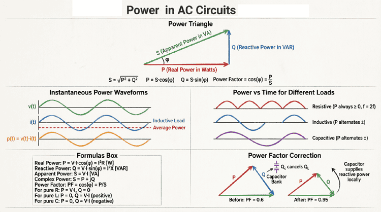
However, the source must still supply current to establish the magnetic field. This circulating energy is called Reactive Power ($Q_L$), measured in Volt-Amperes Reactive (VAR).
The formula for inductive reactive power is:
$Q_L = V_{RMS} \times I_{RMS} = I_{RMS}^2 \times X_L$
While reactive power does no useful mechanical work, it is absolutely essential. Without it, we could not create the magnetic fields required to run electric motors, operate transformers, or generate AC power in the first place.
Does an inductor consume real power?
A pure inductor consumes zero real power (Watts). Instead, it exchanges energy with the AC source, storing it in a magnetic field during one quarter-cycle and returning it during the next. This circulating energy is called Reactive Power, measured in VAR (Volt-Amperes Reactive).
Real-World Inductors: Winding Resistance and the Q Factor
In textbook theory, we often assume “pure” inductors with zero resistance. In the real world, an inductor is made of physical wire (copper or aluminum), which inherently has some DC resistance. This is called Winding Resistance ($R_W$).
When AC current flows through an inductor, two things happen:
- The inductance ($L$) creates inductive reactance ($X_L$), causing a 90° phase shift and storing reactive power.
- The winding resistance ($R_W$) acts like a standard resistor, dissipating some energy as heat and consuming real power.
The Quality Factor (Q)
To determine how “close to perfect” an inductor is, engineers calculate its Quality Factor ($Q$). The Q factor is the ratio of the energy stored in the magnetic field (reactive power) to the energy lost as heat in the winding resistance (real power).
$Q = \frac{X_L}{R_W}$
- A high Q factor (e.g., Q > 100) means the winding resistance is very small compared to the reactance. The inductor acts very much like a “pure” inductor. This is critical in radio frequency (RF) tuning circuits where energy loss must be minimized.
- A low Q factor means the wire resistance is significant, and the component behaves more like a resistor-inductor (RL) series combination, wasting more energy as heat.
Combining Inductors in AC Circuits
When designing circuits, you often need to combine multiple inductors. Assuming they are physically far enough apart that their magnetic fields do not interact (no mutual inductance), they combine exactly like resistors.
Series Inductors
When inductors are connected in series, their total inductance is simply the sum of the individual inductances. The total inductive reactance is also the sum of the individual reactances.
$L_{Total} = L_1 + L_2 + L_3 + …$
$X_{L(Total)} = X_{L1} + X_{L2} + X_{L3} + …$
Parallel Inductors
When inductors are connected in parallel, the total inductance is calculated using the reciprocal formula, just like parallel resistors.
$\frac{1}{L_{Total}} = \frac{1}{L_1} + \frac{1}{L_2} + \frac{1}{L_3} + …$
Practical Applications of Inductive Reactance
The unique frequency-dependent nature of inductive reactance makes inductors incredibly versatile in modern electronics and power systems.
1. RF Chokes
An “RF Choke” (Radio Frequency Choke) is an inductor specifically designed to block high-frequency AC signals while allowing DC or low-frequency signals to pass freely. Because $X_L$ increases with frequency, a choke presents a massive resistance (high reactance) to high-frequency noise or radio signals, effectively “choking” them off, while offering almost zero resistance to the DC power supply.
2. AC Filters and Crossovers
Inductors are the backbone of electronic filters. In a Low-Pass Filter, an inductor is placed in series with the load. It allows low frequencies to pass but blocks high frequencies. In audio speaker systems, inductors are used in crossover networks to route low-frequency bass signals to the “woofer” speakers while blocking the high-frequency treble signals.
3. Tuned Circuits (LC Tanks)
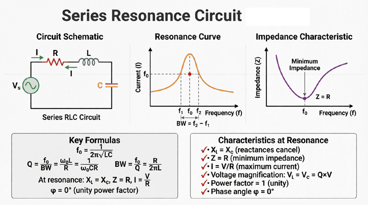
When an inductor ($L$) and a capacitor ($C$) are connected together, they form a “tank circuit.” Because inductive reactance increases with frequency and capacitive reactance decreases with frequency, there is one specific frequency where $X_L$ exactly equals $X_C$. This is the Resonant Frequency. At resonance, the circuit can oscillate and selectively amplify a specific radio frequency while rejecting all others. This is the fundamental principle behind how your radio tunes into a specific station.
4. Transformers and Motors
Without inductance, the modern power grid would not exist. Transformers rely on mutual inductance—the ability of a changing AC current in one coil to induce a voltage in a nearby coil via a shared magnetic field. Similarly, AC induction motors rely on the phase shift and magnetic fields created by inductive reactance to generate the rotating magnetic field that spins the motor shaft.
The Power of Magnetic Fields
As we conclude this comprehensive series on AC circuit theory, we have traveled from the basic sine wave to the profound depths of inductive reactance. We have seen how the simple act of coiling a wire transforms a passive conductor into a dynamic component that interacts with the fundamental forces of electromagnetism.
Key takeaways from our exploration of AC inductance include:
- Inductance ($L$) is the property of a conductor to oppose changes in current, governed by Faraday’s and Lenz’s laws.
- Inductive Reactance ($X_L = 2\pi f L$) is the specific opposition to AC current, which increases as frequency or inductance increases.
- In a pure inductive circuit, voltage leads current by 90 degrees, creating a phase shift that is critical for AC power analysis.
- Pure inductors consume zero real power, instead exchanging reactive power ($Q_L$) with the source to sustain their magnetic fields.
- Real-world inductors possess winding resistance, which is quantified by the Quality Factor (Q).
- Inductors are essential for chokes, filters, tuned circuits, transformers, and motors, making them indispensable in modern electrical engineering.
From the massive transformers stepping down voltage for your home, to the tiny inductors filtering noise in your smartphone’s processor, the principles of AC inductance and inductive reactance are at work. By mastering these concepts, you have not just learned a set of mathematical formulas; you have unlocked the physical language of the electromagnetic world.