CAVITY KLYSTRON
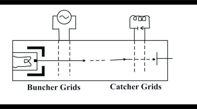
If we have a device, which generates a beam of electrons, we notice that the electrons flow in a smooth steady stream at a particular uniform velocity. The area of the tube that the electron beam travels down is known as the DRIFT TUBE. If we insert, within the beam a grid, we can use this grid to control the beam. As we increase the positive potential on the grid, (assuming that we do not go over a certain potential which is less than the anode voltage), the electrons will be attracted to the grid, and by means of attraction, will be accelerated. On the other hand, should we decrease the potential, making it more negative, it will have the opposite effect on the beam, and try to slow down the electrons? Now using this theory, we attempt an experiment:
We insert two grids, properly spaced for our experiment, and apply an alternating current source to the grids, such that as one grid swings positive, the other swings negative. This would mean that the electrons which are approaching the positive going grid will be speeding up, as the ones approaching the negative going grid will be slowing down. As the phase of the AC cycle changes 180 degrees, we have the same effect, only backwards. The result would be a sort of “slinky” effect, where the electron beam is interrupted, and moves along in bursts. This effect is known as velocity modulation. The electrons are moving in clusters or bunching up.
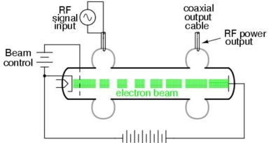
Two-Cavity Klystron
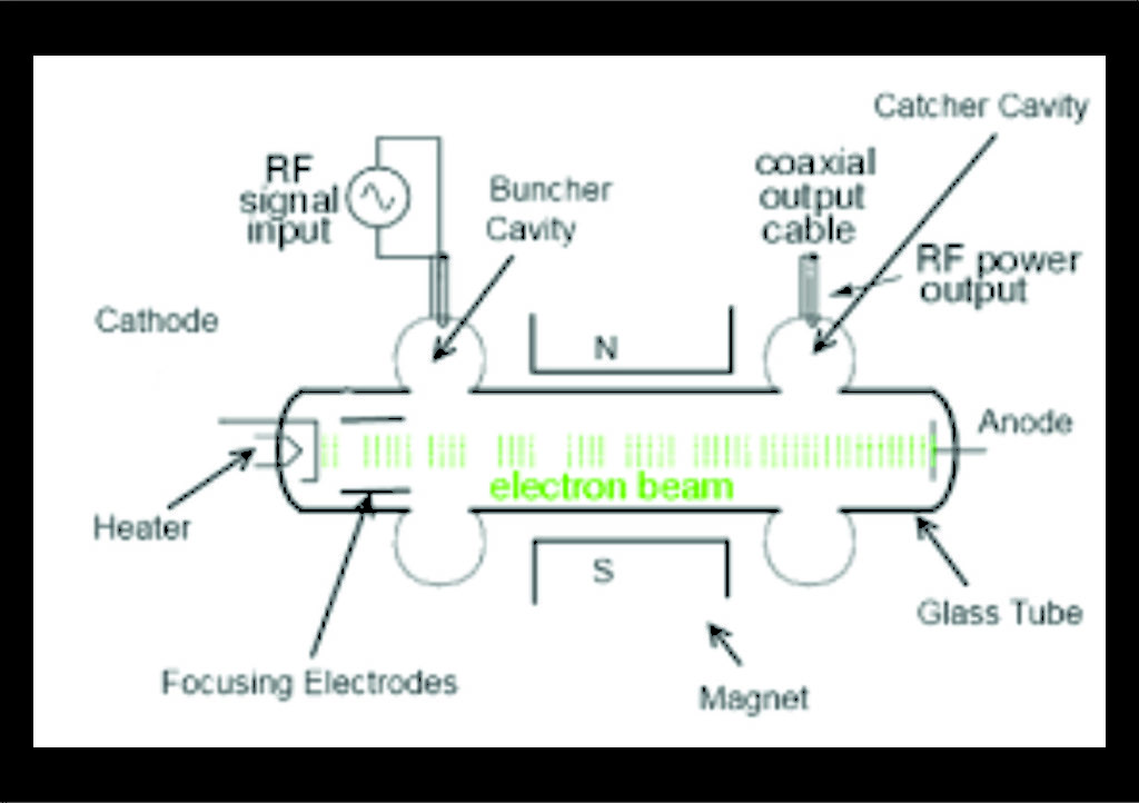
A Klystron is a microwave vacuum tube using cavity resonators to produce velocity modulation of the electron beam and produce amplification. The concept of a two-cavity Klystron. The vacuum tube consists of a cathode, which is heated by a filament. At a very high temperature, the cathode emits electrons. These negative electrons are attracted by a positive plate or collector. Thus, current flow is established between the cathode and the collector inside the evacuated tube.
The electrons emitted by the cathode are focused into a very narrow stream by electrostatic and electromagnetic techniques. The sharply focused beam of electrons is then focused to ass through the centers of two cavity resonators. The cavity is open in the center area. The microwave signal to amplify is applied to the first cavity through a coupling loop. This sets up electric and magnetic fields in the cavity which affect the electron beam. Specifically they cause the electrons to speed up and slow down as they pass through the cavity. On one half cycle, the electrons are speeded up, while on the next half cycle of the input, they are slowed down. The effect of this is to create bunches of electrons that are one-half wavelength apart in the drift space between the cavities. This speeding up and slowing down of the electron beam is known as velocity modulation. Since the input cavity produces bunches of electrons, it is commonly referred to as the buncher cavity. The bunched electrons move on through the tube since they are attracted by the positive collector. They then pass through the center of another cavity known as the catcher cavity. These bunched electrons move toward the collector in clouds of alternately dense and spares areas. We can say that the electron beam is density modulated. As the bunches of electrons pass through the catcher cavity, it excites the cavity into oscillation at the resonant frequency. Therefore, dc energy in the electron beam is converted into RF energy at the cavity frequency. Thus, amplification takes place. The output is extracted from the catcher cavity with a loop.
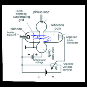
Reflex Klystron
The reflex Klystron is sometimes called the “Klystron Oscillator”. A Reflex Klystron uses the single cavity. The cathode emitters’ electrons, which are accelerated forward by an accelerating grid with a positive voltage on it and focused into a narrow beam. The cavity also acts as an anode and has a high positive voltage applied to it, which causes the electron beam to accelerate. Because of the large momentum obtain by the electrons. They overshoot from the gap in the cavity, and continue to move towards the next electrode, which they in fact never reach. Actually when the electrons, passes through the cavity and undergo velocity modulation which produces electron bunches. The electron bunches move toward the repeller plate, which is made negative with respect to the cathode. This causes the electrons to be repelled rather than attracted as they are by a positive collector in a standard Klystron. The result is that the bunched electrons are forced back through the cavity. The distance between the repeller and the cavity is chosen such that the repelled electron bunches will reach the cavity at the proper time to be in synchronization. Because of this, they deliver energy to the cavity. The result is oscillation at the cavity frequency. The cavity itself is made positive so that the electrons are ultimately attracted by the cavity and cause direct current flow in the external circuit. A coupling loop in the cavity removes the RF energy.