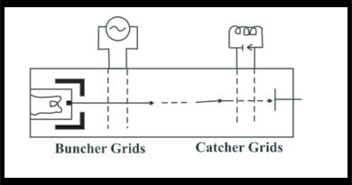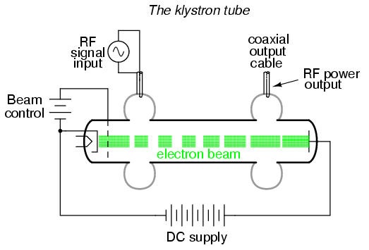
Multi-Cavity Klystron
Klystrons are also constructed with additional cavities between the bunches and catcher cavities. These intermediate cavities produce further bunching which causes increased amplification of the signal. If the bunches cavities are tuned off the center frequency from the input and output cavities, they have the effect of broadening the bandwidth of the tube. The frequency of operation of a Klystron is set by the sizes of the input and output cavities. Since cavities typically have high Q’s. Their bandwidth is limited. By lowering the Q’s of the cavities and by introducing intermediate cavities, wider bandwidth operation can be achieved.
Multi-cavity Magnetron
The name magnetron is a conjunction of the words magnet electron and identifies one of the major components, a very powerful magnet. The second major component is a cylindrical copper block, drilled and channeled. The center opening is called the interaction chamber.
The holes drilled around the outer edge have a diameter equal to one-half wavelength at the operating frequency and are called resonant chambers. There will always be an even number of resonant chambers, usually no less than 6 and no more than 16. With the magnetron used as a diode, the copper block becomes the anode, and a directly heating cathode is placed at the center of the interaction space. The chamber is sealed with top and bottom cover plates and the air is drawn out to form a vacuum. The output connection is a wire loop in one of the chambers that feeds to a coaxial cable fitting on the side wall of the block anode. Because the anode is exposed to the user, it is placed at ground potential and the cathode is at a high negative potential. The magnetron will only operate as an oscillator (never as an amplifier) and find its greatest use as a power oscillator. The start of oscillations is due to random phenomenon in the electron space charge and in the cavity resonators. The cavity oscillations produce electric fields which fringe out into the interaction space from the slots in the anode structure.
Energy is transferred from the radial dc field to the r-f field by interaction of the electrons with the fringing r-f field. The first orbit of the electron A. the transfer of energy is from the electron to the tangential component of the r-f field. The electron comes to a stop and is again accelerated by the radial d-c field. This orbit of the electron is adjacent to the next cavity slot. If the rf field across the cavity slot has changed phase by 180°, the direction of the if field is opposite the direction shown, and the electron is again slowed down and give up energy to the r-f field. The dotted line indicates that energy transfer from the electron to the tangential component of the rf field will occur at each cavity if the: electron moves in synchronism with the r-f field. The electron gives up most of its energy before it finally terminates on the anode surface. The electron at B absorbs energy from the field and is accelerated a and quickly returned to the cathode. There is a net delivery of energy to the cavity resonators because electrons that absorb energy from the r-f field are quickly returned to the cathode. There is a net delivery of energy to the cavity resonators because the electrons that absorb energy from the r-f field are quickly returned to the cathode, whereas the energy in the rational component of motion of the electron in the retarding r-f fields remains practically unaffected, and the electron may orbit around the cathode many times.
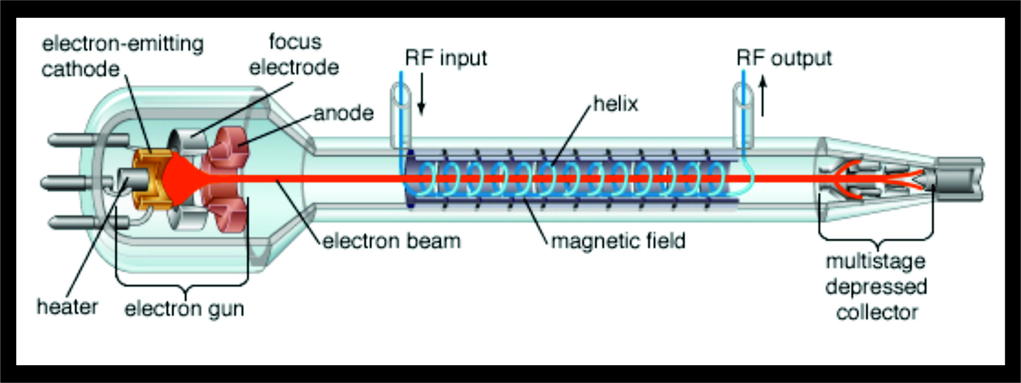
Traveling Wave Tube (TWT)
It consists of a cathode and filament heater plus an anode that is biased positively to accelerate the electron beam forward and to focus it into a narrow beam.
The electrons are attracted by a positive plate called the collector to which is applied a very high dc voltage.
The unique feature of the TWT is a helix or coil that surrounds the length of the tube. The electron beam passes through the center or axis of the helix.
The microwave signal to he amplified is applied to the end of the helix near the cathode, and the output is taken from the end of the helix near the collector.
The propagation of the RF signal along the helix is made approximately equal to the velocity of the electron beam from cathode to collector. The structure of the helix is such that the wave traveling along it is slightly slower than that of the electron beam.
The passage of the microwave signal down the helix produces electric and magnetic fields that will interact with the electron beam. The effect on the electron beam is similar to that on a Klystron. The electromagnetic field produced by the helix, causes the electrons to be speeded-up and slowed down/This produces velocity modulation of the beam, which produces density modulation. Density modulation, of course, causes, bunches of electrons. These bunches of electron travel down the length of the tube toward the collector. Since the density modulated electron beam is essentially in steps with the electromagnetic wave traveling down the helix, the electron bunches induce voltages into the helix which reinforce the voltage already present there, The result is that the strength of the electromagnetic field on the helix increases as the wave travels down the tube toward the collector. At the end of the helix, the signal is considerably amplified. Co-axial cable or wave-guide structures are used to extract energy from the helix.
Backward Wave Oscillators
Backward Wave Oscillator (BWO) is an extension of the traveling wave tube. The construction is modified to connect the helix to the collector which causes a sever mismatch and generates a high VSWR. The attenuator at the center if used in TWT is removed, and oscillations are allowed to as a result of the reflected wave.
The only connection of the oscillator is at the cathode end of the tube. The cathode construction is in the form of a ring that sends out a hollow beam with maximum intensity close to the helix to intensify oscillations. So the rf energy moves and build up in a direction opposite to that of the electron beam and is coupled out at the gun end of the tube via helix terminal.
Power and Efficiency
Power of the order of mill-watts are readily achieved in backward wave oscillators at frequencies as great as 100,000 MHz. At lower frequencies relatively large powers can be developed, nearly 100 watts at 3000 MHz. Efficiencies obtainable in backward – wave oscillators are of the same order of magnitude as those realized with TWT. When the powers are low the efficiencies will be of the order of a few percent or loss. With higher powers, efficiencies exceeding 10 percent have been realized experimentally, and higher values appear to be possible.