Passive Components in AC Circuits
Passive Components in AC Circuits: R, L, and C Behaviour
Introduction to Passive Components in AC Systems
Passive components form the fundamental building blocks of all electrical and electronic circuits. The three primary passive components—resistors (R), inductors (L), and capacitors (C)—behave in fundamentally different ways when subjected to alternating current (AC) compared to direct current (DC). Understanding these differences is crucial for designing filters, power supplies, signal processing circuits, and power distribution systems.
In DC circuits, the behavior of passive components is relatively straightforward:
- Resistors oppose current flow according to Ohm’s Law
- Inductors act as short circuits (once steady-state is reached)
- Capacitors act as open circuits (once fully charged)
However, in AC circuits, the continuously changing voltage and current reveal the dynamic characteristics of these components:
- Resistors maintain constant opposition regardless of frequency
- Inductors oppose changes in current, with opposition increasing with frequency
- Capacitors oppose changes in voltage, with opposition decreasing with frequency
These frequency-dependent behaviors, combined with the phase shifts introduced by inductors and capacitors, create a rich landscape of circuit possibilities. From simple filters to complex resonant systems, the interaction of passive components in AC circuits enables virtually all modern electrical and electronic systems.
This comprehensive guide will explore the behavior of each passive component in AC circuits, their impedance characteristics, phase relationships, frequency response, and practical applications, complete with visual diagrams and step-by-step examples.
How do passive components behave in AC circuits?
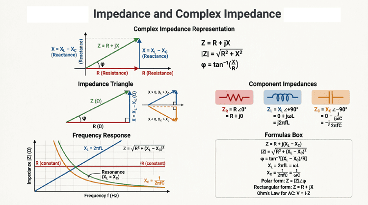
In AC circuits, resistors oppose current uniformly with no phase shift, inductors oppose current changes with voltage leading current by 90°, and capacitors oppose voltage changes with current leading voltage by 90°. Inductive reactance increases with frequency (XL = 2πfL), while capacitive reactance decreases with frequency (XC = 1/2πfC).
Resistors in AC Circuits
Fundamental Behavior
Resistors are the simplest passive components, and their behavior in AC circuits mirrors their DC behavior. A resistor opposes the flow of current according to Ohm’s Law, regardless of whether the current is AC or DC.
Key Characteristics:
- Frequency Independence:
- Resistance (R) remains constant regardless of frequency
- Unlike inductors and capacitors, resistors don’t exhibit frequency-dependent behavior
- A 100Ω resistor is 100Ω at DC, 60 Hz, 1 kHz, or 1 MHz
- No Phase Shift:
- Voltage and current are in phase (0° phase difference)
- When voltage reaches its peak, current also reaches its peak
- When voltage crosses zero, current also crosses zero
- Power Dissipation:
- Resistors convert electrical energy to heat
- Real power is dissipated: $P = I_{RMS}^2 \times R$
- No reactive power (Q = 0)
Mathematical Representation
For a resistor in an AC circuit:
Impedance:
$Z_R = R$
The impedance is purely real (no imaginary component).
Voltage-Current Relationship:
If $v(t) = V_m \sin(\omega t)$, then:
$i(t) = \frac{V_m}{R} \sin(\omega t)$
Both voltage and current have the same phase angle.
Phasor Form:
$\mathbf{V} = \mathbf{I} \times R$
Where both V and I are phasors with the same angle.
Power in Resistive AC Circuits
Instantaneous Power:
$p(t) = v(t) \times i(t) = V_m I_m \sin^2(\omega t)$
Average (Real) Power:
$P = V_{RMS} \times I_{RMS} = I_{RMS}^2 \times R = \frac{V_{RMS}^2}{R}$
Reactive Power:
$Q = 0 \text{ VAR}$
Resistors consume only real power; they don’t store or return energy.
Power Factor:
$PF = 1.0$ (unity)
Since voltage and current are in phase, the power factor is perfect.
What is the impedance of a resistor in AC circuits?
The impedance of a resistor is simply its resistance value: Z = R. Unlike inductors and capacitors, a resistor’s impedance doesn’t change with frequency, and it causes no phase shift between voltage and current (they remain in phase).
Inductors in AC Circuits
Fundamental Behavior
Inductors store energy in magnetic fields and oppose changes in current. This opposition, called inductive reactance, varies with frequency and introduces a characteristic 90° phase shift between voltage and current.
Key Characteristics:
- Frequency Dependence:
- Inductive reactance increases linearly with frequency
- $X_L = 2\pi f L$
- At DC (f = 0), XL = 0 (inductor acts as short circuit)
- At high frequencies, XL is large (inductor acts as open circuit)
- Phase Shift:
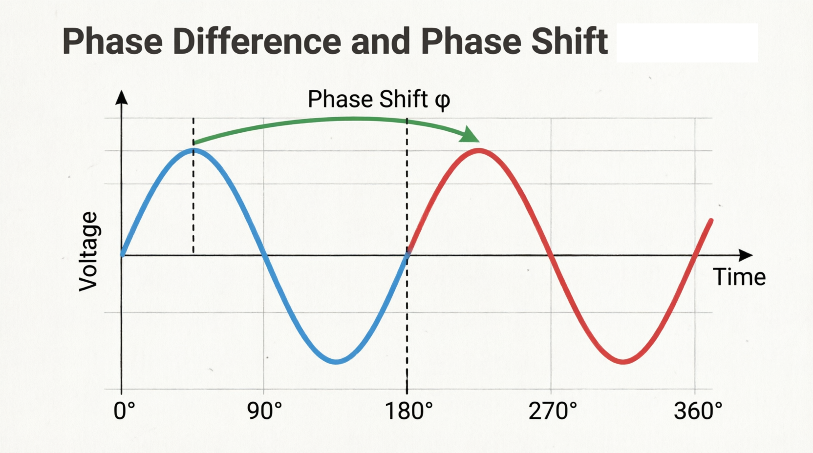
- Voltage leads current by 90° (or current lags voltage by 90°)
- This phase relationship is fundamental to inductor behavior
- Remember: ELI (E leads I in L)
- Energy Storage:
- Stores energy in magnetic field: $W = \frac{1}{2} L I^2$
- Returns energy to source each cycle
- Net energy consumption = 0 (ideal inductor)
Inductive Reactance
The opposition an inductor presents to AC current is called inductive reactance (XL):
$X_L = 2\pi f L = \omega L$
Where:
- XL = Inductive reactance in ohms (Ω)
- f = Frequency in hertz (Hz)
- L = Inductance in henrys (H)
- ω = Angular frequency (rad/s) = 2πf
- π = Pi (≈ 3.14159)
Example:
For a 10 mH inductor at 60 Hz:
$X_L = 2\pi \times 60 \times 0.010$
$X_L = 3.77 \Omega$
At 1 kHz:
$X_L = 2\pi \times 1000 \times 0.010$
$X_L = 62.8 \Omega$
The reactance increases 16.7× when frequency increases from 60 Hz to 1 kHz.
Mathematical Representation
Impedance:
$Z_L = jX_L = j\omega L$
The impedance is purely imaginary (positive j indicates inductive).
Voltage-Current Relationship:
$v(t) = L \frac{di(t)}{dt}$
For sinusoidal current $i(t) = I_m \sin(\omega t)$:
$v(t) = \omega L I_m \cos(\omega t) = \omega L I_m \sin(\omega t + 90°)$
This shows voltage leads current by 90°.
Phasor Form:
$\mathbf{V} = \mathbf{I} \times jX_L$
Multiplication by j represents a +90° phase shift.
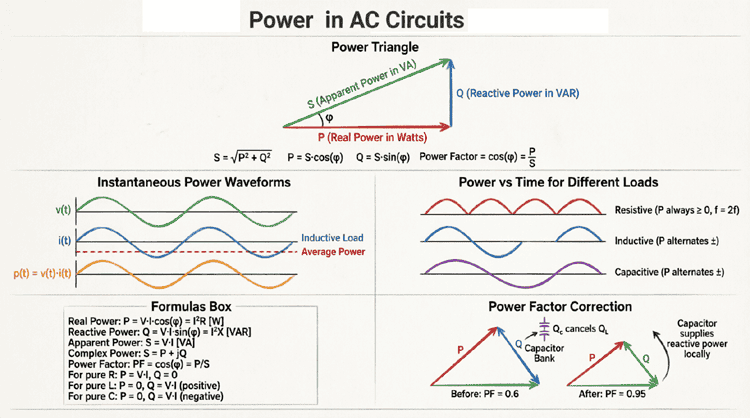
Power in Inductive AC Circuits
Instantaneous Power:
Oscillates at twice the supply frequency, alternating between positive and negative.
Average (Real) Power:
$P = 0 \text{ W}$ (ideal inductor)
No net energy is consumed; energy is stored and returned each cycle.
Reactive Power:
$Q_L = V_{RMS} \times I_{RMS} = I_{RMS}^2 \times X_L = \frac{V_{RMS}^2}{X_L}$
Measured in VAR (Volt-Amperes Reactive).
By convention, inductive reactive power is positive (Q > 0).
Power Factor:
$PF = 0$ (lagging)
Pure inductors have zero power factor (all reactive, no real power).
Capacitors in AC Circuits
Fundamental Behavior
Capacitors store energy in electric fields and oppose changes in voltage. This opposition, called capacitive reactance, varies inversely with frequency and introduces a 90° phase shift opposite to that of inductors.
Key Characteristics:
- Frequency Dependence:
- Capacitive reactance decreases as frequency increases
- $X_C = \frac{1}{2\pi f C}$
- At DC (f = 0), XC = ∞ (capacitor acts as open circuit)
- At high frequencies, XC is small (capacitor acts as short circuit)
- Phase Shift:
- Current leads voltage by 90° (or voltage lags current by 90°)
- Opposite to inductor behavior
- Remember: ICE (I leads E in C)
- Energy Storage:
- Stores energy in electric field: $W = \frac{1}{2} C V^2$
- Returns energy to source each cycle
- Net energy consumption = 0 (ideal capacitor)
Capacitive Reactance
The opposition a capacitor presents to AC current is called capacitive reactance (XC):
$X_C = \frac{1}{2\pi f C} = \frac{1}{\omega C}$
Where:
- XC = Capacitive reactance in ohms (Ω)
- f = Frequency in hertz (Hz)
- C = Capacitance in farads (F)
- ω = Angular frequency (rad/s) = 2πf
Example:
For a 10 μF capacitor at 60 Hz:
$X_C = \frac{1}{2\pi \times 60 \times 10 \times 10^{-6}}$
$X_C = \frac{1}{0.00377}$
$X_C = 265 \Omega$
At 1 kHz:
$X_C = \frac{1}{2\pi \times 1000 \times 10 \times 10^{-6}}$
$X_C = 15.9 \Omega$
The reactance decreases 16.7× when frequency increases from 60 Hz to 1 kHz (opposite to inductor behavior).
Mathematical Representation
Impedance:
$Z_C = -jX_C = \frac{1}{j\omega C} = \frac{-j}{\omega C}$
The impedance is purely imaginary (negative j indicates capacitive).
Voltage-Current Relationship:
$i(t) = C \frac{dv(t)}{dt}$
For sinusoidal voltage $v(t) = V_m \sin(\omega t)$:
$i(t) = \omega C V_m \cos(\omega t) = \omega C V_m \sin(\omega t + 90°)$
This shows current leads voltage by 90°.
Phasor Form:
$\mathbf{I} = \mathbf{V} \times j\omega C$
Or: $\mathbf{V} = \mathbf{I} \times (-jX_C)$
Multiplication by -j represents a -90° phase shift.
Power in Capacitive AC Circuits
Instantaneous Power:
Oscillates at twice the supply frequency, alternating between positive and negative.
Average (Real) Power:
$P = 0 \text{ W}$ (ideal capacitor)
No net energy is consumed; energy is stored and returned each cycle.
Reactive Power:
$Q_C = V_{RMS} \times I_{RMS} = I_{RMS}^2 \times X_C = \frac{V_{RMS}^2}{X_C}$
Measured in VAR.
By convention, capacitive reactive power is negative (Q < 0).
Power Factor:
$PF = 0$ (leading)
Pure capacitors have zero power factor (all reactive, no real power).
What is the difference between inductive and capacitive reactance?
Inductive reactance (XL = 2πfL) increases with frequency and causes voltage to lead current by 90°. Capacitive reactance (XC = 1/2πfC) decreases with frequency and causes current to lead voltage by 90°. Inductors oppose current changes; capacitors oppose voltage changes.
Frequency Response of Passive Components
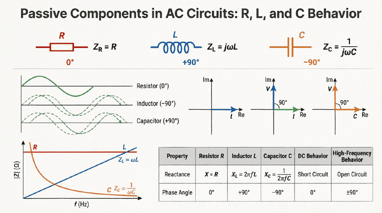
Impedance vs. Frequency
The impedance of passive components varies differently with frequency:
Resistor:
- $Z_R = R$ (constant)
- Horizontal line on impedance vs. frequency graph
- No frequency dependence
Inductor:
- $Z_L = j2\pi f L$
- Linear increase with frequency
- Starts at 0 at DC, increases indefinitely
Capacitor:
- $Z_C = \frac{1}{j2\pi f C}$
- Inverse relationship with frequency
- Starts at at DC, decreases toward 0
Comparative Analysis
Practical Frequency Response Summary
| Component | At DC (f=0) | At Low Frequency | At High Frequency |
|---|---|---|---|
| Resistor | R | R | R |
| Inductor | Short (0Ω) | Low XL | Open (∞Ω) |
| Capacitor | Open (∞Ω) | High XC | Short (0Ω) |
This table reveals why:
- Inductors are used in low-pass filters (pass DC, block high frequencies)
- Capacitors are used in high-pass filters (block DC, pass high frequencies)
- Resistors provide frequency-independent behavior
Phase Relationships Summary
Visualizing Phase Shifts
The phase relationships between voltage and current for each component are fundamental to AC circuit analysis:
Resistor:
- Voltage and current in phase (0°)
- Phasor diagram: V and I point in same direction
Inductor:
- Voltage leads current by 90°
- Current lags voltage by 90°
- Phasor diagram: V points up, I points right
Capacitor:
- Current leads voltage by 90°
- Voltage lags current by 90°
- Phasor diagram: I points up, V points right
Mnemonic Devices
Remember the phase relationships with these mnemonics:
“ELI the ICE man”:
- ELI: In an inductor (L), E (voltage) leads I (current)
- ICE: In a capacitor (C), I (current) leads E (voltage)
“CIVIL”:
- C: In a Capacitor, I leads V
- L: In an inductor (L), V leads I
Practical Applications of Passive Components
Filter Circuits
Low-Pass Filter (RL or RC):
- Passes low frequencies, attenuates high frequencies
- Used in audio systems to remove high-frequency noise
- Power supply filtering
High-Pass Filter (RL or RC):
- Passes high frequencies, attenuates low frequencies
- Used in audio crossovers for tweeters
- AC coupling (blocking DC)
Band-Pass Filter (RLC):
- Passes a specific frequency range
- Used in radio tuners
- Communication systems
Band-Stop Filter (RLC):
- Blocks a specific frequency range
- Used to eliminate interference
- Notch filters
Power Factor Correction
Capacitors are used to correct lagging power factor caused by inductive loads:
- Industrial motor facilities
- Fluorescent lighting systems
- Reduces current draw and energy costs
Energy Storage
Inductors:
- Switching power supplies
- DC-DC converters
- Energy storage in magnetic field
Capacitors:
- Power supply smoothing
- Camera flash circuits
- Energy storage in electric field
Impedance Matching
Passive components match impedances between circuit stages:
- Maximum power transfer
- Minimize reflections in RF systems
- Audio amplifier design
Summary and Conclusion
Passive components—resistors, inductors, and capacitors—form the foundation of AC circuit theory. Each component exhibits unique characteristics that make it indispensable for specific applications:
Key takeaways from this guide:
- Resistors:
- Impedance: Z = R (frequency-independent)
- Phase: Voltage and current in phase (0°)
- Power: Consumes real power only (P > 0, Q = 0)
- Applications: Current limiting, voltage division, heating
- Inductors:
- Impedance: Z = jXL = j2πfL (increases with frequency)
- Phase: Voltage leads current by 90°
- Power: Stores/returns energy (P = 0, Q > 0)
- Applications: Filters, transformers, motors, energy storage
- Capacitors:
- Impedance: Z = -jXC = 1/(j2πfC) (decreases with frequency)
- Phase: Current leads voltage by 90°
- Power: Stores/returns energy (P = 0, Q < 0)
- Applications: Filters, power factor correction, coupling, energy storage
- Frequency Response:
- Inductors block high frequencies, pass low frequencies
- Capacitors block low frequencies, pass high frequencies
- Resistors are frequency-independent
- Phase Relationships:
- Remember “ELI the ICE man” for phase shifts
- Critical for power calculations and circuit analysis
Understanding the behavior of passive components in AC circuits enables you to design filters, analyze power systems, create oscillators, and solve complex electrical engineering problems. Whether you’re working with power distribution, signal processing, or electronic circuit design, mastering these fundamentals is essential for success.
As you continue your electrical engineering journey, remember that these three simple components, when combined in various configurations, can create incredibly sophisticated and powerful circuits. The principles outlined in this guide form the bedrock upon which all advanced AC circuit analysis is built.