Average Voltage Tutorial
Average Voltage Tutorial: AC Average Value Calculations
Introduction to Average Voltage
When analyzing alternating current (AC) waveforms, understanding the average voltage is essential for designing rectifiers, power supplies, and measurement systems. Unlike DC voltage, which remains constant, AC voltage continuously varies in a sinusoidal pattern, spending equal time in positive and negative regions.
The concept of “average voltage” in AC circuits has important nuances that distinguish it from the more commonly used RMS voltage. While a complete AC cycle has an average value of zero (because positive and negative halves cancel each other), the half-cycle average provides valuable information about the waveform’s characteristics and is crucial for rectifier design and certain measurement applications.
Understanding average voltage is particularly important when working with:
- Rectifier circuits (converting AC to DC)
- Power supply design
- Analog meter movements
- Signal processing applications
- Waveform analysis
This comprehensive guide will explore the theory, mathematics, and practical applications of average voltage, complete with visual diagrams and step-by-step calculations.
What is Average Voltage?
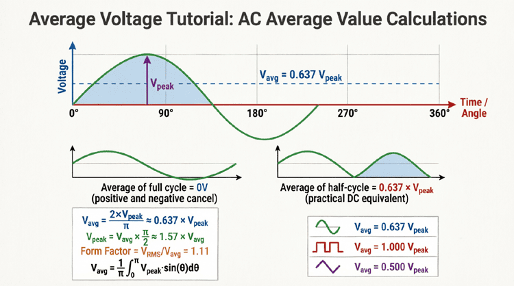
Average voltage is the arithmetic mean of instantaneous voltage values over a specified time period. For a complete AC cycle, the average is zero. For a half-cycle (positive or negative half), the average voltage equals 0.637 times the peak voltage. This half-cycle average is crucial for rectifier design and certain measurement applications.
Understanding Average Value Concepts
The Challenge with AC Averages
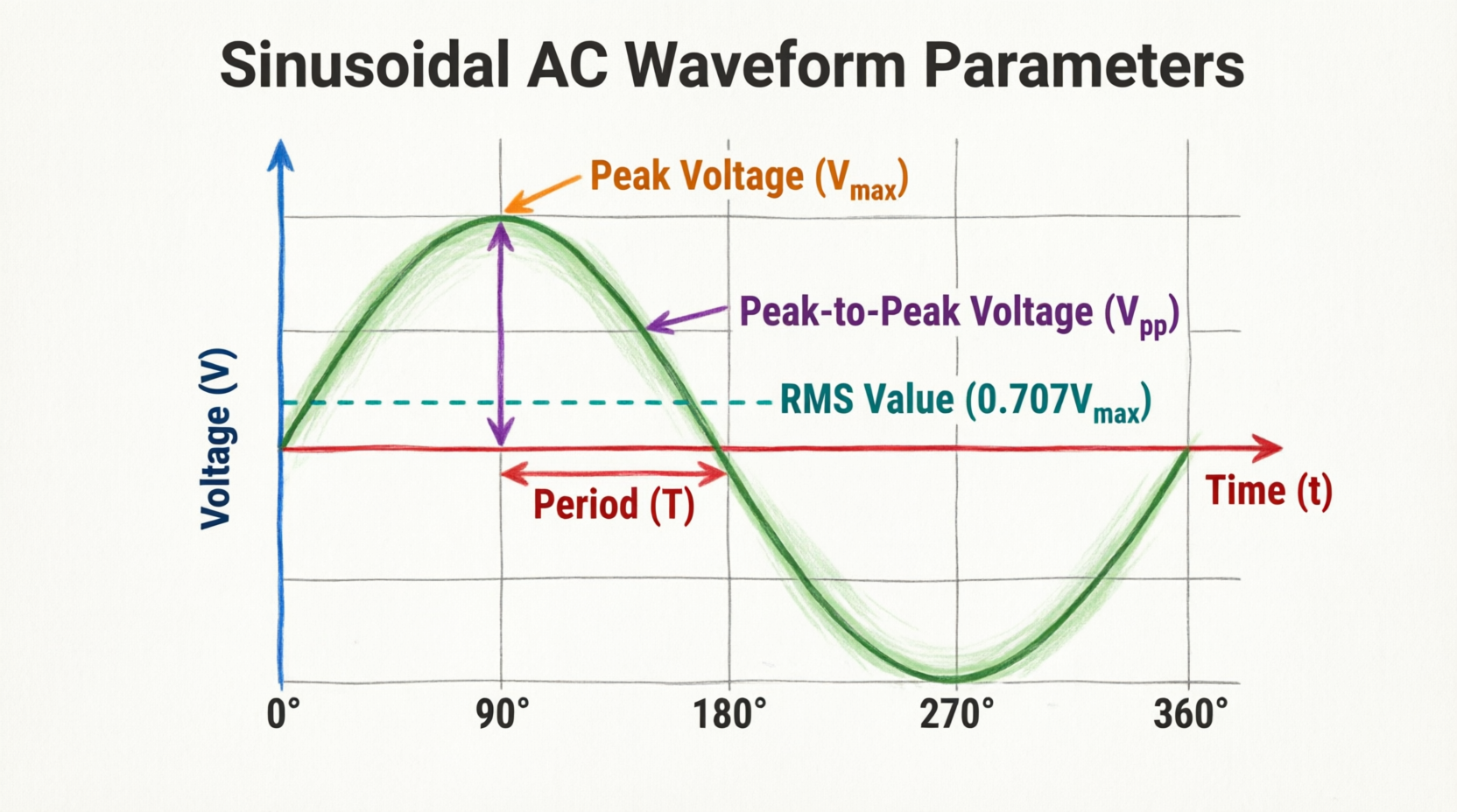
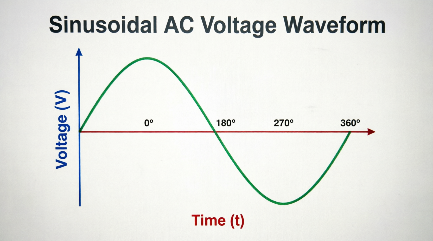
When we talk about the “average” of an AC waveform, we must be specific about what we’re averaging. Consider a standard sinusoidal AC voltage:
- During the positive half-cycle, voltage ranges from 0V to +Vpeak and back to 0V
- During the negative half-cycle, voltage ranges from 0V to -Vpeak and back to 0V
- Over one complete cycle, every positive value has a corresponding negative value
Mathematically:
If we calculate the average over a complete cycle:
$V_{avg(full\ cycle)} = \frac{1}{T} \int_0^T v(t) dt = 0$
The average is zero because the positive and negative halves perfectly cancel each other out.
Why Zero Average is Misleading
While mathematically correct, saying “the average AC voltage is zero” doesn’t tell us anything useful about the waveform’s ability to do work or deliver power. A 120V RMS household outlet and a dead battery would both have an “average voltage of zero” if we use the full-cycle definition!
This is why we use different averaging approaches:
- Half-Cycle Average: Average over only the positive (or negative) half-cycle
- Full-Wave Rectified Average: Average of the absolute value of the waveform
- RMS Value: Root mean square (covered in the previous article)
Each serves different purposes in electrical engineering.
The Half-Cycle Average
The half-cycle average is the most commonly used average value for AC waveforms. It’s calculated by averaging the instantaneous voltage values over only the positive half-cycle (or equivalently, the negative half-cycle).
For a sinusoidal waveform:
$V_{avg(half-cycle)} = \frac{2}{\pi} \times V_{peak} = V_{peak} \times 0.637$
Where:
- $V_{avg}$ = Half-cycle average voltage
- $V_{peak}$ = Peak (maximum) voltage
- $\pi$ = Pi (approximately 3.14159)
- 2/π = Approximately 0.6366 or 0.637
This value represents the DC voltage that would transfer the same total charge during the half-cycle period.
What is the half-cycle average of a sine wave?
The half-cycle average voltage of a sinusoidal waveform equals 0.637 times the peak voltage (or 2/π × Vpeak). For example, if peak voltage is 100V, the half-cycle average is 63.7V. This is different from RMS voltage (which would be 70.7V for the same waveform).
Mathematical Derivation of Average Voltage
Calculating Half-Cycle Average
To understand where the 0.637 factor comes from, let’s derive it mathematically.
For a sinusoidal voltage $v(t) = V_{peak} \sin(\omega t)$, the average over a half-cycle (from 0 to π radians) is:
$V_{avg} = \frac{1}{\pi} \int_0^\pi V_{peak} \sin(\theta) d\theta$
Solving this integral:
$V_{avg} = \frac{V_{peak}}{\pi} [-\cos(\theta)]_0^\pi$
$V_{avg} = \frac{V_{peak}}{\pi} [-\cos(\pi) – (-\cos(0))]$
$V_{avg} = \frac{V_{peak}}{\pi} [-(-1) – (-1)]$
$V_{avg} = \frac{V_{peak}}{\pi} [1 + 1]$
$V_{avg} = \frac{2V_{peak}}{\pi}$
$V_{avg} = V_{peak} \times \frac{2}{\pi} = V_{peak} \times 0.637$
Full-Wave Rectified Average
When an AC waveform is full-wave rectified (both positive and negative halves are converted to positive), the average value is the same as the half-cycle average:
$V_{avg(full-wave\ rectified)} = V_{peak} \times 0.637$
This is because full-wave rectification essentially “folds” the negative half-cycle up to become positive, so we’re averaging two identical positive half-cycles.
Half-Wave Rectified Average
For half-wave rectification (only the positive half-cycle passes, negative is blocked), the average is calculated over the entire period but only the positive half contributes:
$V_{avg(half-wave\ rectified)} = \frac{V_{peak}}{\pi} = V_{peak} \times 0.318$
This is exactly half of the full-wave rectified average because we’re averaging over the full period but only getting contribution from half the time.
Average Voltage vs. RMS Voltage
Key Differences
It’s crucial to understand the difference between average voltage and RMS voltage:
| Characteristic | Average Voltage | RMS Voltage |
|---|---|---|
| Definition | Arithmetic mean of instantaneous values | Root mean square of instantaneous values |
| Full-cycle (sine) | 0 | Vpeak × 0.707 |
| Half-cycle (sine) | Vpeak × 0.637 | Vpeak × 0.707 |
| Physical meaning | Average level over time | Equivalent DC heating effect |
| Used for | Rectifier design, charge transfer | Power calculations, equipment ratings |
| Relationship | Vavg = 0.9 × VRMS (for sine) | VRMS = 1.11 × Vavg (for sine) |
The Form Factor
The ratio of RMS voltage to average voltage is called the form factor:
Form Factor = $\frac{V_{RMS}}{V_{avg}} = \frac{0.707}{0.637} = 1.11$
For a pure sine wave, the RMS value is always 1.11 times the half-cycle average value.
This relationship is important for analog meters that measure average value but are calibrated to display RMS values (assuming a sine wave).
What is the relationship between average and RMS voltage?
For a pure sine wave, RMS voltage = 1.11 × average voltage (half-cycle). Or conversely, average voltage = 0.9 × RMS voltage. For example, 120V RMS has a half-cycle average of 108V. This ratio (1.11) is called the form factor.
Average Voltage Relationships and Conversions
Key Formulas for Sinusoidal Waveforms
For a pure sine wave, here are the essential relationships:
From Peak Voltage:
- $V_{avg} = V_{peak} \times 0.637$
- $V_{RMS} = V_{peak} \times 0.707$
- $V_{pp} = V_{peak} \times 2$
From RMS Voltage:
- $V_{avg} = V_{RMS} \times 0.9$
- $V_{peak} = V_{RMS} \times 1.414$
- $V_{pp} = V_{RMS} \times 2.828$
From Average Voltage:
- $V_{RMS} = V_{avg} \times 1.11$
- $V_{peak} = V_{avg} \times 1.57$
- $V_{pp} = V_{avg} \times 3.14$
Quick Reference Conversion Table
| If you know: | Multiply by: | To get: |
|---|---|---|
| $V_{peak}$ | 0.637 | $V_{avg}$ (half-cycle) |
| $V_{peak}$ | 0.707 | $V_{RMS}$ |
| $V_{RMS}$ | 0.9 | $V_{avg}$ (half-cycle) |
| $V_{RMS}$ | 1.414 | $V_{peak}$ |
| $V_{avg}$ | 1.11 | $V_{RMS}$ |
| $V_{avg}$ | 1.57 | $V_{peak}$ |
| $V_{peak}$ | 0.318 | $V_{avg}$ (half-wave rectified) |
Practical Examples and Calculations
Example 1: Calculating Average Voltage from Peak
Problem: A sinusoidal AC voltage has a peak value of 170V. Calculate the half-cycle average voltage and compare it to the RMS voltage.
Solution:
Given: $V_{peak} = 170\text{V}$
Calculate Half-Cycle Average:
$V_{avg} = V_{peak} \times 0.637$
$V_{avg} = 170 \times 0.637$
$V_{avg} = 108.3\text{V}$
Calculate RMS Voltage:
$V_{RMS} = V_{peak} \times 0.707$
$V_{RMS} = 170 \times 0.707$
$V_{RMS} = 120.2\text{V}$
Verify Relationship:
$V_{RMS} = V_{avg} \times 1.11$
$120.2 = 108.3 \times 1.11$ ✓
Interpretation: This is standard North American household voltage: 170V peak, 120V RMS, 108V average.
Example 2: Full-Wave Rectifier Output
Problem: A full-wave rectifier is connected to a 24V RMS AC source. Calculate the average DC output voltage (ignoring diode voltage drops).
Solution:
Given: $V_{RMS} = 24\text{V}$
Step 1: Find Peak Voltage
$V_{peak} = V_{RMS} \times 1.414$
$V_{peak} = 24 \times 1.414$
$V_{peak} = 33.94\text{V}$
Step 2: Calculate Average Output (Full-Wave)
$V_{avg} = V_{peak} \times 0.637$
$V_{avg} = 33.94 \times 0.637$
$V_{avg} = 21.6\text{V DC}$
Alternative Method:
$V_{avg} = V_{RMS} \times 0.9$
$V_{avg} = 24 \times 0.9$
$V_{avg} = 21.6\text{V DC}$
Interpretation: The rectifier produces an average DC output of 21.6V from a 24V RMS AC input.
Example 3: Half-Wave Rectifier Output
Problem: A half-wave rectifier is connected to the same 24V RMS AC source. Calculate the average DC output voltage.
Solution:
Given: $V_{RMS} = 24\text{V}$
Find Peak Voltage:
$V_{peak} = 24 \times 1.414 = 33.94\text{V}$
Calculate Average Output (Half-Wave):
$V_{avg} = V_{peak} \times 0.318$
$V_{avg} = 33.94 \times 0.318$
$V_{avg} = 10.8\text{V DC}$
Notice: Half-wave rectification produces exactly half the average voltage of full-wave rectification (10.8V vs 21.6V).
Example 4: Determining Peak from Average Measurement
Problem: An analog meter measures the average value of an AC waveform as 45V. Assuming a sine wave, calculate the peak and RMS voltages.
Solution:
Given: $V_{avg} = 45\text{V}$
Calculate Peak Voltage:
$V_{peak} = V_{avg} \times 1.57$
$V_{peak} = 45 \times 1.57$
$V_{peak} = 70.65\text{V}$
Calculate RMS Voltage:
$V_{RMS} = V_{avg} \times 1.11$
$V_{RMS} = 45 \times 1.11$
$V_{RMS} = 49.95\text{V} \approx 50\text{V}$
Visualizing Average Voltage
The Sine Wave and Average Level
Understanding average voltage visually helps clarify the concept:
The average voltage (63.7V in this example for a 100V peak sine wave) represents the height of a rectangle that would have the same area as the area under the sine wave curve over the half-cycle period.
Geometric Interpretation
The average voltage can be visualized as:
Average = (Area under the curve) / (Time period)
For a half-cycle of a sine wave:
- The area under the curve from 0 to π radians equals $2 \times V_{peak}$
- The time period is π radians
- Therefore: Average = $2V_{peak} / \pi = 0.637 \times V_{peak}$
Average Voltage in Rectifier Circuits
Full-Wave Bridge Rectifier
A full-wave bridge rectifier converts both halves of the AC cycle to DC. The output waveform consists of consecutive positive half-cycles.
Average Output Voltage:
$V_{DC(avg)} = V_{peak} \times 0.637$
Or in terms of RMS input:
$V_{DC(avg)} = V_{RMS} \times 0.9$
Accounting for Diode Drops:
In practice, each diode has a forward voltage drop (typically 0.7V for silicon diodes). In a bridge rectifier, current flows through two diodes at any time:
$V_{DC(avg)} = (V_{peak} – 1.4V) \times 0.637$
Half-Wave Rectifier
A half-wave rectifier only passes the positive half-cycle, blocking the negative half.
Average Output Voltage:
$V_{DC(avg)} = V_{peak} \times 0.318$
Or in terms of RMS input:
$V_{DC(avg)} = V_{RMS} \times 0.45$
Accounting for Diode Drop:
$V_{DC(avg)} = (V_{peak} – 0.7V) \times 0.318$
Ripple Voltage and Filtering
The average voltage represents the DC component of the rectified output. However, the actual output contains ripple—an AC component superimposed on the DC average.
Adding a filter capacitor smooths the output, raising the average voltage closer to the peak value:
Without capacitor: $V_{avg} = 0.637 \times V_{peak}$
With large capacitor: $V_{avg} \approx V_{peak}$ (minus diode drops)
Measuring Average Voltage
Analog Meter Movements
Traditional analog multimeters use a moving coil meter movement (D’Arsonval movement) that responds to average current. However, these meters are calibrated to display RMS values for AC measurements.
How it works:
- The meter measures average current through the coil
- For a sine wave: $I_{avg} = I_{RMS} / 1.11$
- The meter scale is multiplied by 1.11 to display RMS
- This assumes a pure sine wave!
Limitation: If the waveform is not a pure sine wave, the reading will be incorrect because the form factor (1.11) only applies to sine waves.
Digital Multimeters
Modern digital multimeters use different techniques:
1. Average-Responding DMMs:
- Measure average value
- Multiply by 1.11 to display RMS
- Accurate only for sine waves
- Less expensive
2. True RMS DMMs:
- Calculate actual RMS using sampling
- Accurate for any waveform
- More expensive
- Essential for distorted waveforms
Oscilloscope Measurements
Oscilloscopes can directly display and measure average voltage:
Manual Measurement:
- Display the waveform
- Measure peak voltage
- Calculate: $V_{avg} = V_{peak} \times 0.637$
Automatic Measurement:
Modern digital oscilloscopes have built-in measurement functions that can directly calculate and display average voltage over a selected time period.
Average Voltage for Non-Sinusoidal Waveforms
Different Waveforms, Different Averages
The 0.637 factor applies only to sine waves. Other waveform shapes have different average-to-peak relationships:
Square Wave (symmetrical):
- Half-cycle average = Peak voltage
- $V_{avg} = V_{peak}$
- Average factor = 1.0
Triangle Wave:
- Half-cycle average = 0.5 × Peak voltage
- $V_{avg} = V_{peak} \times 0.5$
- Average factor = 0.5
Sawtooth Wave:
- Half-cycle average = 0.5 × Peak voltage
- $V_{avg} = V_{peak} \times 0.5$
- Average factor = 0.5
Pulse Wave (Duty Cycle D):
- Average = Peak × Duty Cycle
- $V_{avg} = V_{peak} \times D$
- Where D is between 0 and 1
Importance of Waveform Shape
When measuring or calculating average voltage, knowing the waveform shape is critical. Using the sine wave factor (0.637) for a square wave would give an error of 36.3%!
Practical Applications of Average Voltage
1. Power Supply Design
Average voltage is fundamental in designing DC power supplies:
- Determines the DC output level from rectifiers
- Helps select appropriate filter capacitors
- Calculates voltage regulation requirements
- Specifies transformer secondary voltage
2. Battery Charging
Battery chargers often use rectified AC. The average voltage determines:
- Charging current
- Charging time
- Whether the voltage is sufficient to charge the battery
3. Analog Signal Processing
In analog circuits, average voltage is used for:
- DC restoration circuits
- Clamping circuits
- Peak detection
- Signal demodulation
4. Motor Control
DC motor speed is proportional to average voltage:
- Phase-controlled rectifiers adjust average voltage
- PWM (Pulse Width Modulation) controls average voltage
- Speed control systems rely on average voltage calculations
5. Instrumentation
Many measurement systems use average detection:
- Light meters
- Sound level meters
- RF field strength meters
- Analog panel meters
Common Mistakes and Misconceptions
Mistake 1: Confusing Average with RMS
Wrong: “The average voltage is 120V, so that’s the RMS value.”
Correct: “The average voltage is 108V, and the RMS voltage is 120V.”
Always specify which value you’re referring to!
Mistake 2: Using Full-Cycle Average for Power
Wrong: “The average voltage is zero, so no power is delivered.”
Correct: “The full-cycle average is zero, but we use RMS or half-cycle average for power calculations.”
Mistake 3: Applying Sine Wave Factors to Other Waveforms
Wrong: “This square wave has 100V peak, so average = 100 × 0.637 = 63.7V”
Correct: “This square wave has 100V peak, so average = 100V (factor is 1.0 for square waves)”
Misconception: Average Voltage Determines Heating
Wrong: “Average voltage determines power dissipation.”
Correct: “RMS voltage determines power dissipation and heating effects. Average voltage is useful for rectifier design and charge transfer calculations.”
Summary and Conclusion
Average voltage is a fundamental concept in AC circuit analysis with specific applications in rectifier design, power supply engineering, and measurement systems. While it differs from RMS voltage, both values are essential for different aspects of electrical engineering.
Key takeaways from this guide include:
- Definition: Average voltage is the arithmetic mean of instantaneous values over a specified period
- Full-Cycle Average: Zero for symmetrical AC waveforms
- Half-Cycle Average: $V_{avg} = V_{peak} \times 0.637$ for sine waves
- Relationship to RMS: $V_{RMS} = V_{avg} \times 1.11$ (form factor for sine waves)
- Rectifier Applications:
- Full-wave: $V_{DC} = V_{peak} \times 0.637$
- Half-wave: $V_{DC} = V_{peak} \times 0.318$
- Measurement: Analog meters measure average but display RMS (assuming sine wave)
- Waveform Dependence: Average factors vary with waveform shape
Understanding average voltage equips you to design efficient rectifiers, analyze power supplies, and interpret meter readings accurately. Whether you’re building a DC power supply, troubleshooting a motor control circuit, or designing signal processing equipment, the principles of average voltage are essential tools in your electrical engineering toolkit.
As you continue your studies, remember that average voltage and RMS voltage serve different purposes: average voltage relates to charge transfer and rectifier output, while RMS voltage relates to power delivery and heating effects. Mastering both concepts provides a complete understanding of AC circuit behavior.