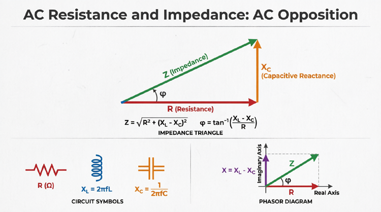
Complex Numbers and Phasors
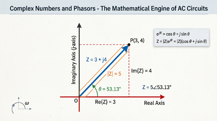
Complex Numbers and Phasors: The Mathematical Engine of AC Circuits
Why Do We Need “Imaginary” Numbers?
When you first hear the term “complex numbers” or “imaginary numbers” in an electrical engineering class, it is normal to feel a sense of dread. In standard arithmetic, the square root of a negative number is impossible. Yet, in the world of Alternating Current (AC) circuits, these “imaginary” numbers are not just a mathematical quirk—they are the absolute foundation of power systems, motor control, and signal processing.
Why? Because AC circuits deal with two distinct types of energy transfer simultaneously: Real Power (which does actual work, like turning a motor shaft) and Reactive Power (which sustains the magnetic and electric fields inside components). These two types of power exist at exactly 90 degrees to each other in the time domain.
Standard 1D arithmetic (real numbers) can only handle quantities that are in phase. To handle quantities that are 90 degrees out of phase, we need a 2D number system. Enter Complex Numbers. By mapping AC circuits onto the complex plane, engineers can use elegant algebra to solve problems that would otherwise require impossible calculus. This guide will dive deep into the mathematics of complex numbers, Euler’s identity, complex conjugates, and the calculation of complex power.
Why are complex numbers used in AC circuits?
Complex numbers are used in AC circuits because they provide a 2D mathematical system to represent both the magnitude and the 90-degree phase shifts of voltage and current. The “real” part represents resistance/real power, while the “imaginary” part represents reactance/reactive power.
The Complex Plane and the ‘j’ Operator
To understand complex numbers, we must abandon the standard 1D number line and step into the 2D Complex Plane (also known as the Argand Plane).
The Real and Imaginary Axes
The complex plane consists of two perpendicular axes:
- The Real Axis (Horizontal): Represents standard, measurable quantities. In AC circuits, this axis represents Resistance (R) and Real Power (P).
- The Imaginary Axis (Vertical): Represents quantities that are 90 degrees out of phase with the real axis. In AC circuits, this axis represents Reactance (X) and Reactive Power (Q).
Any point on this plane can be described by a complex number, combining a real component and an imaginary component.
Deep Dive into the ‘j’ Operator
As mentioned in previous articles, electrical engineers use $j$ instead of $i$ for the imaginary unit to avoid confusion with current ($i$). By definition:
$j = \sqrt{-1}$
Therefore, $j^2 = -1$
The true magic of the $j$ operator is its geometric meaning: multiplying by $j$ rotates a phasor exactly 90° counter-clockwise. If we apply $j$ repeatedly, we get a fascinating cycle of rotation:
- $j^1 = j$ (Rotated 90° CCW – Points UP)
- $j^2 = -1$ (Rotated 180° – Points LEFT)
- $j^3 = -j$ (Rotated 270° CCW – Points DOWN)
- $j^4 = 1$ (Rotated 360° – Back to the start, pointing RIGHT)
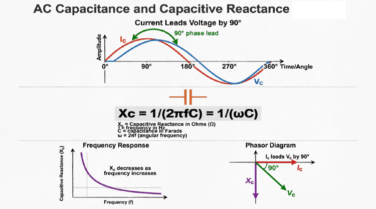
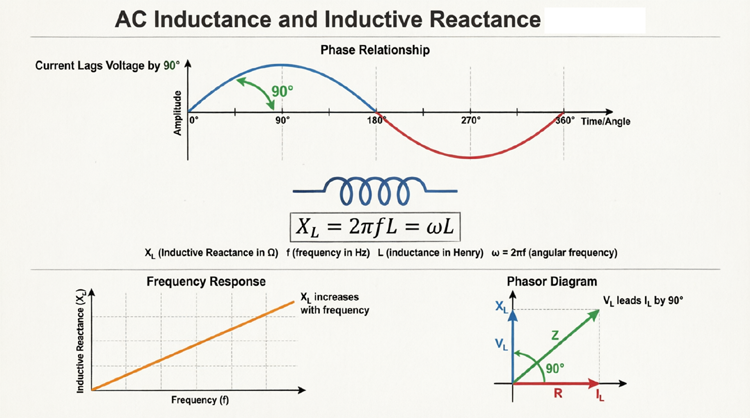
This rotational property is exactly why $j$ is used to represent inductive reactance ($+jX_L$, pointing up) and capacitive reactance ($-jX_C$, pointing down).
What does multiplying by ‘j’ do to a phasor?
Multiplying a phasor by the imaginary operator ‘j’ rotates the phasor exactly 90 degrees counter-clockwise in the complex plane, without changing its magnitude. This perfectly models the 90-degree phase shift introduced by pure inductors and capacitors.
The Three Forms of Complex Numbers
To perform advanced AC calculations, you must be fluent in the three different ways to express a complex number. Each form has specific mathematical advantages.
1. Rectangular (Algebraic) Form
This form expresses the complex number by its horizontal (real) and vertical (imaginary) projections.
Equation: $Z = R + jX$
- Best for: Addition and subtraction. You simply add the real parts together and the imaginary parts together.
2. Polar (Trigonometric) Form
This form expresses the complex number by its total length (magnitude) and its angle from the positive real axis.
Equation: $Z = |Z| \angle \theta$ or $Z = |Z|(\cos\theta + j\sin\theta)$
- Best for: Multiplication and division. You multiply/divide the magnitudes and add/subtract the angles.
3. Exponential Form (Euler’s Identity)
This is the most advanced and elegant form, bridging trigonometry and exponential functions. It relies on Euler’s Formula, one of the most beautiful equations in mathematics:
$e^{j\theta} = \cos\theta + j\sin\theta$
Therefore, a complex number in exponential form is written as:
Equation: $Z = |Z|e^{j\theta}$
Why is this useful? In advanced circuit analysis involving differential equations (like transient analysis of RLC circuits), the exponential form allows engineers to use the standard rules of exponents ($e^A \times e^B = e^{A+B}$) rather than dealing with messy trigonometric identities.
What is Euler’s Formula in AC circuits?
Euler’s formula states that $e^{j\theta} = \cos\theta + j\sin\theta$. In AC circuits, it allows engineers to represent rotating phasors and sinusoidal waveforms as exponential functions, vastly simplifying the calculus required to solve differential equations in RLC circuits.
Complex Conjugates and Division
When analyzing AC circuits, you will frequently need to divide complex numbers, especially when calculating total impedance in parallel circuits or finding current using Ohm’s Law ($I = V / Z$).
Dividing complex numbers in rectangular form is notoriously difficult because you cannot have an imaginary number in the denominator. To solve this, we use the Complex Conjugate.
What is a Complex Conjugate?
The complex conjugate of a number is created by simply flipping the sign of the imaginary part.
If you have a complex impedance $Z = R + jX$, its complex conjugate is $Z^* = R – jX$.
Geometrically, the complex conjugate is the exact mirror image of the original number, reflected across the Real (horizontal) axis.
Rationalizing the Denominator
To divide two complex numbers in rectangular form, you multiply both the top (numerator) and the bottom (denominator) by the complex conjugate of the denominator.
The Math Trick: When you multiply a complex number by its conjugate, the imaginary parts cancel out perfectly, leaving a purely real number!
$(R + jX)(R – jX) = R^2 – (jX)^2 = R^2 – (j^2)(X^2) = R^2 – (-1)(X^2) = R^2 + X^2$
Example Calculation:
Divide $V = 100 + j50$ by $Z = 4 + j3$.
- Find the conjugate of $Z$: $Z^* = 4 – j3$.
- Multiply top and bottom by $Z^*$:
$I = \frac{(100 + j50)(4 – j3)}{(4 + j3)(4 – j3)}$ - Expand the numerator: $(400 – j300 + j200 – j^2 150) = 400 – j100 + 150 = 550 – j100$
- Expand the denominator: $4^2 + 3^2 = 16 + 9 = 25$
- Final Result: $I = \frac{550 – j100}{25} = 22 – j4 \text{ Amps}$.
By using the complex conjugate, we successfully divided the numbers without ever needing to convert to polar form!
Visualizing the Complex Planes in AC Circuits
To truly internalize complex numbers, we must visualize how they map to physical circuit properties. Let’s look at two critical colorful diagrams.
Diagram 1: The Complex Impedance Plane
Diagram Description: The Crimson Red horizontal axis represents Resistance (R). The Electric Blue vertical axis represents Inductive Reactance (+jX_L), while the Lime Green downward axis represents Capacitive Reactance (-jX_C). The Golden Vector represents a specific impedance (Z = 5 + j4) located in the first quadrant, indicating a net inductive circuit with a positive phase angle (θ).
Diagram 2: The Complex Power Plane
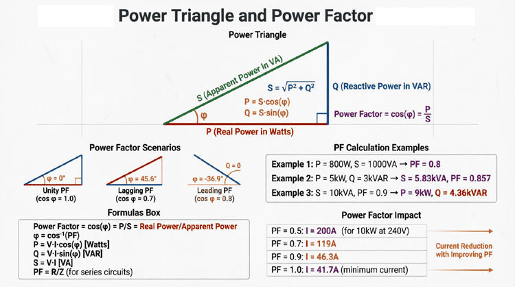
Diagram Description: The Bright Cyan horizontal axis represents Real Power (P) measured in Watts. The Magenta vertical axis represents Inductive Reactive Power (+jQ_L) measured in VARs. The Neon Yellow vector represents Apparent Power (S), showing the total power drawn from the source. The angle θ between P and S is the power factor angle.
Complex Power: The Ultimate Application
The most powerful application of complex numbers in AC circuits is the calculation of Complex Power ($S$).
In DC circuits, power is simply $P = V \times I$. In AC circuits, because voltage and current can be out of phase, we have three types of power:
- Real Power (P): Measured in Watts (W). Does actual work.
- Reactive Power (Q): Measured in Volt-Amperes Reactive (VAR). Sustains magnetic/electric fields.
- Apparent Power (S): Measured in Volt-Amperes (VA). The total power supplied by the source.
Using complex numbers, we can combine all three into a single, elegant equation:
$S = P + jQ$
Calculating Complex Power
To calculate complex power, we use the complex voltage ($V$) and the complex conjugate of the current ($I^*$).
$S = V \times I^*$
Why the conjugate? If we just multiplied $V \times I$, the phase angles would add together, giving us the wrong power angle. By using the conjugate $I^*$, we subtract the current angle from the voltage angle ($\theta_V – \theta_I$), which correctly yields the phase difference ($\theta$) between voltage and current!
Example Calculation:
A load draws a current of $I = 10 \angle -30^\circ A$ from a source voltage of $V = 120 \angle 15^\circ V$. Find the Complex Power ($S$), Real Power ($P$), and Reactive Power ($Q$).
Step 1: Find the complex conjugate of the current.
$I = 10 \angle -30^\circ A$
$I^* = 10 \angle +30^\circ A$ (Flip the sign of the angle)
Step 2: Calculate Complex Power ($S$).
$S = V \times I^*$
$S = (120 \angle 15^\circ) \times (10 \angle 30^\circ)$
$S = 1200 \angle (15^\circ + 30^\circ)$
$S = 1200 \angle 45^\circ \text{ VA}$
Step 3: Convert to Rectangular Form to find P and Q.
$P = 1200 \times \cos(45^\circ) = 1200 \times 0.707 = 848.5 \text{ W}$
$Q = 1200 \times \sin(45^\circ) = 1200 \times 0.707 = 848.5 \text{ VAR}$
Final Answer:
$S = 848.5 + j848.5 \text{ VA}$
Because $Q$ is positive ($+j$), the reactive power is inductive, meaning the load is lagging.
How do you calculate Complex Power in AC circuits?
Complex Power (S) is calculated by multiplying the complex RMS voltage (V) by the complex conjugate of the RMS current (I). The formula is S = V × I. The result is expressed as S = P + jQ, where P is real power and Q is reactive power.
Admittance: The Reciprocal of Impedance
When analyzing complex parallel AC circuits, calculating total impedance using the reciprocal formula ($1/Z_{total} = 1/Z_1 + 1/Z_2$) requires tedious complex division. To simplify this, engineers use Admittance ($Y$).
Admittance is simply the reciprocal of Impedance, just as Conductance ($G$) is the reciprocal of Resistance ($R$).
$Y = 1 / Z$
Admittance is also a complex number, measured in Siemens (S) or Mhos (℧). It is expressed as:
$Y = G + jB$
Where:
- $G$ is Conductance (the real part).
- $B$ is Susceptance (the imaginary part).
By converting impedances to admittances, adding parallel branches becomes as simple as adding complex numbers in rectangular form:
$Y_{total} = Y_1 + Y_2 + Y_3$
Once you find $Y_{total}$, you simply take the reciprocal to find $Z_{total}$. This technique saves massive amounts of time in complex network analysis.
Example: Parallel Impedance using Complex Math
Let’s put everything together in a realistic scenario.
Problem: Two impedances are connected in parallel across a 100V source.
$Z_1 = 3 + j4 \Omega$ (An RL branch)
$Z_2 = 0 – j10 \Omega$ (A purely capacitive branch)
Calculate the total current drawn from the source using Admittance.
Step 1: Convert Impedances to Admittances ($Y = 1/Z$)
To do this easily, convert $Z$ to polar form first, then invert.
$Z_1 = 3 + j4 = 5 \angle 53.13^\circ \Omega$
$Y_1 = 1 / (5 \angle 53.13^\circ) = 0.2 \angle -53.13^\circ \text{ S}$
Convert $Y_1$ to rectangular: $Y_1 = 0.12 – j0.16 \text{ S}$
$Z_2 = 10 \angle -90^\circ \Omega$
$Y_2 = 1 / (10 \angle -90^\circ) = 0.1 \angle +90^\circ \text{ S}$
Convert $Y_2$ to rectangular: $Y_2 = 0 + j0.1 \text{ S}$
Step 2: Add Admittances
$Y_{total} = Y_1 + Y_2$
$Y_{total} = (0.12 – j0.16) + (0 + j0.10)$
$Y_{total} = 0.12 – j0.06 \text{ S}$
Step 3: Calculate Total Current
Using Ohm’s law with Admittance: $I = V \times Y$
Let $V = 100 \angle 0^\circ V$.
$I = (100 \angle 0^\circ) \times (0.12 – j0.06)$
First, convert $Y_{total}$ to polar:
$|Y| = \sqrt{0.12^2 + (-0.06)^2} = \sqrt{0.0144 + 0.0036} = \sqrt{0.018} \approx 0.134 \text{ S}$
$\theta_Y = \arctan(-0.06 / 0.12) = \arctan(-0.5) \approx -26.56^\circ$
$Y_{total} = 0.134 \angle -26.56^\circ \text{ S}$
Now multiply:
$I = 100 \times 0.134 = 13.4 \text{ A}$
Angle = $0^\circ + (-26.56^\circ) = -26.56^\circ$
$I_{total} = 13.4 \angle -26.56^\circ \text{ Amps}$
The total current is 13.4 Amps, lagging the voltage by 26.56 degrees. By using complex admittance, we bypassed the need for complex division entirely!
Complex numbers are the unsung heroes of electrical engineering. What seems like an abstract mathematical concept—the square root of negative one—is actually the perfect tool for describing the physical reality of alternating current.
By mapping resistance and reactance onto the real and imaginary axes, complex numbers allow us to:
- Use simple algebra instead of differential calculus to solve AC circuits.
- Easily calculate phase shifts using the $j$ operator and Euler’s formula.
- Simplify parallel circuit analysis using Admittance and complex conjugates.
- Combine Real, Reactive, and Apparent power into a single, unified Complex Power equation ($S = P + jQ$).
Mastering complex numbers and phasors transitions you from a student who merely memorizes AC formulas to an engineer who truly understands the deep, mathematical architecture of electrical power. Whether you are designing a microchip filter or balancing a three-phase power grid, the complex plane is the canvas upon which modern electronics are drawn.