Phasor Diagrams and Phasor Algebra
Introduction: The Problem with Sine Waves
In the previous articles, we explored how AC waveforms oscillate over time and how phase shifts occur between voltage and current. If you tried to calculate the total voltage of a series AC circuit by adding up the instantaneous sine wave equations using trigonometry, you would quickly realize it is a mathematical nightmare. Adding sine waves of different amplitudes and phase angles requires complex trigonometric identities that are tedious, time-consuming, and highly prone to error.
In the late 19th century, a brilliant electrical engineer named Charles Proteus Steinmetz introduced a revolutionary concept that changed electrical engineering forever: Phasor analysis.
By transforming time-domain sine waves into rotating vectors in a complex plane, Steinmetz turned impossible trigonometry into simple algebra and geometry. This guide will teach you how to read, draw, and calculate using phasor diagrams and phasor algebra, giving you the ultimate toolkit for AC circuit analysis.
What is a Phasor?
A phasor (phase vector) is a complex number that represents the amplitude and phase angle of a sinusoidal waveform. Instead of tracking a wave’s continuous movement over time, a phasor “freezes” the wave, representing it as a stationary vector in a 2D plane, making AC math significantly easier.
What is a Phasor?
To understand a phasor, we must first revisit the AC generator. Imagine a wire loop rotating counter-clockwise at a constant angular velocity ($\omega$) in a magnetic field. The induced voltage is a sine wave.
Now, imagine looking at this rotating loop straight on from the side. It just looks like a line spinning around a central point. If we draw an arrow from the center to the edge of this spinning circle, that arrow is a phasor.
The “Frozen” Rotation
In reality, this phasor is spinning at the frequency of the AC system (e.g., 60 times a second for a 60Hz system). However, because all phasors in a single AC circuit spin at the exact same speed, their relative positions to one another never change.
Therefore, for the sake of analysis, we “freeze” time at $t = 0$. The phasors stop spinning, and we can analyze them as static vectors on a piece of paper. The length of the vector represents the magnitude (usually the RMS value) of the sine wave, and the angle of the vector represents its phase shift relative to a reference.
The ‘j’ Operator
In mathematics, the imaginary unit is denoted by $i$ (where $i = \sqrt{-1}$). However, in electrical engineering, $i$ is already universally used to represent instantaneous current. To avoid confusion, engineers use the letter $j$ for the imaginary unit.
In phasor algebra, multiplying a vector by $j$ rotates it exactly 90° counter-clockwise. Multiplying by $-j$ rotates it 90° clockwise. This simple rule is the secret engine that makes phasor math work.
Why do we use ‘j’ instead of ‘i’ in AC math?
We use ‘j’ as the imaginary unit ($j = \sqrt{-1}$) in electrical engineering because the letter ‘i’ is already the standard symbol for electrical current. Using ‘j’ prevents confusion in equations involving both complex numbers and current.
Phasor Diagrams: Visualizing AC Circuits
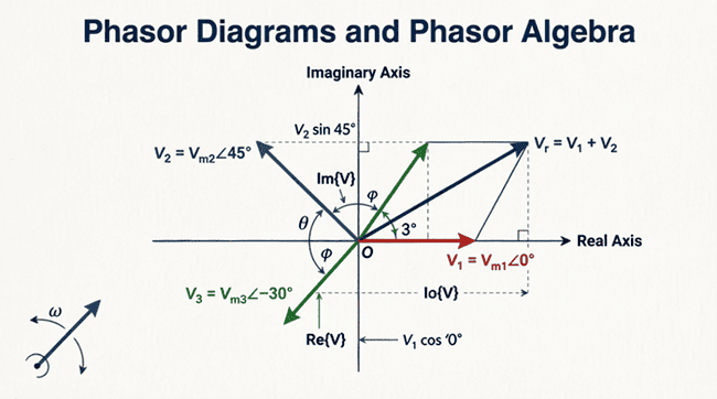
A phasor diagram is a graphical representation of two or more phasors drawn on a complex plane (also known as an Argand diagram). The horizontal axis is the Real axis (x-axis), and the vertical axis is the Imaginary axis (y-axis).
Drawing the Reference Phasor
When drawing a phasor diagram, you must first choose a reference. Usually, the source voltage is chosen as the reference phasor and is drawn pointing directly to the right along the positive Real axis (0° angle). All other voltages and currents are then drawn relative to this reference.
Visualizing Component Phasors
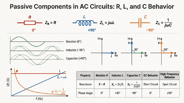
Let’s look at how the basic components (R, L, and C) are represented in a phasor diagram where current ($I$) is the reference (since current is common in series circuits).
Diagram Description: The Electric Blue current phasor is the reference, pointing right (0°). The Cyan resistor voltage ($V_R$) is in phase with the current, so it also points right. The Magenta inductor voltage ($V_L$) leads the current by 90°, pointing straight up. The Lime Green capacitor voltage ($V_C$) lags the current by 90°, pointing straight down.
Phasor Algebra: The Two Forms
To perform calculations, we must translate these visual vectors into mathematical equations. Phasors can be expressed in two primary mathematical forms: Rectangular and Polar. Knowing how to convert between them is the most critical skill in AC math.
1. Rectangular Form (x + jy)
In rectangular form, a phasor is broken down into its horizontal (Real) and vertical (Imaginary) components.
- x represents the real part (resistance or active component).
- y represents the imaginary part (reactance or quadrature component).
Equation: $V = x + jy$
2. Polar Form (r ∠ θ)
In polar form, a phasor is defined by its total magnitude and its angle.
- r represents the magnitude (length of the vector, usually RMS).
- θ (theta) represents the phase angle in degrees or radians.
Equation: $V = r \angle \theta$
Converting Between Forms
You will constantly need to switch between these forms depending on the math operation you are performing.
Polar to Rectangular:
- Real part ($x$) = $r \times \cos(\theta)$
- Imaginary part ($y$) = $r \times \sin(\theta)$
Rectangular to Polar:
- Magnitude ($r$) = $\sqrt{x^2 + y^2}$ (Pythagorean theorem)
- Angle ($\theta$) = $\arctan(y / x)$
How do you convert Polar to Rectangular form?
To convert a phasor from polar ($r \angle \theta$) to rectangular ($x + jy$), calculate the real part using $x = r \cos(\theta)$ and the imaginary part using $y = r \sin(\theta)$. The rectangular form is then written as $x + jy$.
Mathematical Operations with Phasors
The true power of phasor algebra is that it allows us to add, subtract, multiply, and divide AC quantities just like DC values, provided we use the correct mathematical form for each operation.
Addition and Subtraction (Use Rectangular Form)
You cannot simply add the magnitudes of two phasors in polar form if they have different angles. You must convert them to rectangular form first.
Rule: Add the real parts together, and add the imaginary parts together.
$(x_1 + jy_1) + (x_2 + jy_2) = (x_1 + x_2) + j(y_1 + y_2)$
Example: Add $V_1 = 10 + j5$ and $V_2 = 3 – j8$.
$V_{total} = (10 + 3) + j(5 – 8) = 13 – j3$.
Multiplication and Division (Use Polar Form)
Multiplying or dividing phasors in rectangular form requires tedious FOIL methods and complex conjugates. Instead, convert them to polar form.
Rule for Multiplication: Multiply the magnitudes, and add the angles.
$(r_1 \angle \theta_1) \times (r_2 \angle \theta_2) = (r_1 \times r_2) \angle (\theta_1 + \theta_2)$
Rule for Division: Divide the magnitudes, and subtract the angles.
$(r_1 \angle \theta_1) / (r_2 \angle \theta_2) = (r_1 / r_2) \angle (\theta_1 – \theta_2)$
Example: Multiply $V_1 = 10 \angle 30^\circ$ by $I = 2 \angle -15^\circ$.
$V_{total} = (10 \times 2) \angle (30^\circ + (-15^\circ)) = 20 \angle 15^\circ$.
Applying Phasor Algebra to AC Circuits
Let’s apply these rules to actual AC circuits. Ohm’s Law ($V = I \times Z$) and Kirchhoff’s Voltage Law ($V_{total} = V_1 + V_2 + …$) still apply, but we must use phasor math.
The Impedance Triangle
In a series RL circuit, the total opposition to current is Impedance ($Z$). Impedance is a phasor made of Resistance ($R$, the real part) and Inductive Reactance ($X_L$, the positive imaginary part).
Diagram Description: The Crimson Red horizontal vector is Resistance ($R$). The Electric Blue vertical vector is Inductive Reactance ($X_L$). The Golden diagonal vector is the total Impedance ($Z$). The angle $\theta$ between $R$ and $Z$ is the circuit’s phase angle.
Mathematically, this is expressed as:
Rectangular: $Z = R + jX_L$
Polar: $Z = \sqrt{R^2 + X_L^2} \angle \arctan(X_L / R)$
Series RLC Circuit Analysis
In a series RLC circuit, we have Resistance ($R$), Inductive Reactance ($X_L$), and Capacitive Reactance ($X_C$).
Because $X_L$ is represented by $+j$ and $X_C$ is represented by $-j$, they oppose each other. The total reactance ($X$) is simply $X_L – X_C$.
Total Impedance Equation:
$Z = R + j(X_L – X_C)$
Step-by-Step Practical Example
Let’s solve a complete AC circuit problem using phasor algebra to see how all these concepts come together.
Problem Statement:
A series circuit is connected to a 120V (RMS), 60Hz source. The circuit contains a Resistor of $R = 4\Omega$, an Inductor with $X_L = 10\Omega$, and a Capacitor with $X_C = 7\Omega$.
Calculate:
- The total impedance ($Z$) in both rectangular and polar form.
- The total current ($I$) flowing through the circuit.
- The phase angle of the circuit, and state if it is leading or lagging.
Step 1: Calculate Total Impedance ($Z$)
First, write the impedance in rectangular form:
$Z = R + j(X_L – X_C)$
$Z = 4 + j(10 – 7)$
$Z = 4 + j3 \Omega$ (This is the rectangular form)
Now, convert to polar form:
Magnitude $|Z| = \sqrt{4^2 + 3^2} = \sqrt{16 + 9} = \sqrt{25} = 5 \Omega$
Angle $\theta = \arctan(3 / 4) = \arctan(0.75) \approx 36.87^\circ$
$Z = 5 \angle 36.87^\circ \Omega$ (This is the polar form)
Step 2: Calculate Total Current ($I$)
Using Ohm’s Law for AC: $I = V / Z$
Let the source voltage be our reference phasor: $V = 120 \angle 0^\circ V$.
$I = (120 \angle 0^\circ) / (5 \angle 36.87^\circ)$
Using the division rule for polar forms (divide magnitudes, subtract angles):
Magnitude $|I| = 120 / 5 = 24 A$
Angle $\theta_I = 0^\circ – 36.87^\circ = -36.87^\circ$
$I = 24 \angle -36.87^\circ A$
Step 3: Determine Phase Angle and Lead/Lag
The phase angle of the circuit is 36.87°.
Because the current angle (-36.87°) is more negative than the voltage angle (0°), the current reaches its peak after the voltage. Therefore, the current lags the voltage. This makes sense, as the inductive reactance (10Ω) is greater than the capacitive reactance (7Ω), making the circuit net inductive.
Graphical Addition: The Tip-to-Tail Method
While phasor algebra (math) is precise, phasor diagrams (geometry) offer incredible intuitive insights. You can add phasors graphically using the Tip-to-Tail method.
- Draw the first phasor starting from the origin (0,0).
- Draw the second phasor starting from the “tip” (the arrowhead) of the first phasor, keeping its length and angle exactly the same.
- Draw a new vector from the origin (0,0) to the tip of the last phasor. This new vector is the resultant sum.
This graphical method is exactly how early engineers solved AC circuits before calculators existed, using rulers, protractors, and graph paper. Today, it remains a fantastic way to visually verify your mathematical calculations.
The Power of Phasors in Modern Engineering
Phasor diagrams and algebra are not just academic exercises; they are the foundation of modern power systems.
Power Systems and the Grid
In a national power grid, thousands of generators must be synchronized. Before connecting a new generator to the grid, engineers use phasor diagrams to ensure the voltage magnitude, frequency, and phase angle of the generator perfectly match the grid. If the phasors are not aligned, connecting the generator would cause a massive, destructive short circuit.
Phasor Measurement Units (PMUs)
Today, the electrical grid uses advanced sensors called Phasor Measurement Units (PMUs) or “synchrophasors.” These devices use GPS satellites to timestamp phasor measurements across thousands of miles. This allows grid operators to see the exact phase angle of the voltage in New York and California at the exact same microsecond, ensuring the entire continent’s AC power remains perfectly synchronized at 60 Hz.
Conclusion
Phasor diagrams and phasor algebra represent the bridge between the physical reality of AC sine waves and the mathematical tools required to engineer electrical systems. By translating time-varying trigonometric functions into static complex vectors, we unlock the ability to use simple algebra to solve incredibly complex circuit problems.
Key takeaways from this guide include:
- A phasor is a complex number representing the magnitude and phase of a sinusoid, “freezing” its rotation for analysis.
- The $j$ operator represents a 90° counter-clockwise rotation and is used instead of $i$ to avoid confusion with current.
- Rectangular form ($x + jy$) is used for addition and subtraction.
- Polar form ($r \angle \theta$) is used for multiplication and division.
- Phasor diagrams provide a visual, geometric way to understand how voltages and currents interact in R, L, and C circuits.
Mastering phasor algebra is a turning point in your electrical engineering journey. It transforms AC circuit analysis from a daunting maze of calculus into a logical, structured, and highly solvable system of equations. With these tools in your arsenal, you are now fully prepared to tackle complex impedance, AC power calculations, and advanced circuit theorems in the upcoming articles.