AC Capacitance and Capacitive Reactance
Introduction to Capacitors in AC Circuits
Capacitors are fundamental components in electrical and electronic circuits, serving as energy storage devices that play a crucial role in alternating current (AC) systems. Unlike resistors that simply oppose current flow, or inductors that store energy in magnetic fields, capacitors store energy in an electric field created between two conductive plates separated by an insulating material called a dielectric.
In direct current (DC) circuits, a capacitor acts as an open circuit once it becomes fully charged, blocking any further current flow. However, in AC circuits where the voltage continuously changes polarity, the capacitor never reaches a final charged state. Instead, it continuously charges and discharges, allowing AC current to appear to “flow” through it. This behavior creates a unique form of opposition called capacitive reactance, which varies inversely with both frequency and capacitance.
Understanding AC capacitance and capacitive reactance is essential for designing filters, power factor correction systems, timing circuits, and countless other applications. This comprehensive guide will explore the physics of capacitors in AC circuits, the mathematics of capacitive reactance, and the practical applications of these fundamental principles.
What is Capacitive Reactance?
Capacitive reactance (X_C) is the opposition that a capacitor presents to alternating current flow. Unlike resistance, it does not dissipate energy as heat but instead stores and releases energy in an electric field. Capacitive reactance is measured in ohms and decreases as either the frequency or capacitance increases, calculated using the formula X_C = 1/(2πfC).
The Physics of Capacitance
Structure and Operation of a Capacitor
A capacitor consists of two conductive plates (typically made of metal) separated by a dielectric material such as air, ceramic, plastic film, or electrolytic material. When a voltage is applied across the plates, electrons accumulate on one plate (making it negative) while being removed from the other plate (making it positive). This separation of charge creates an electric field in the dielectric material between the plates.
The amount of charge (Q) that a capacitor can store is directly proportional to the applied voltage (V) and is determined by the capacitance (C):
Q = C × V
Where:
- Q = Charge in coulombs (C)
- C = Capacitance in farads (F)
- V = Voltage in volts (V)
Capacitance in AC Circuits
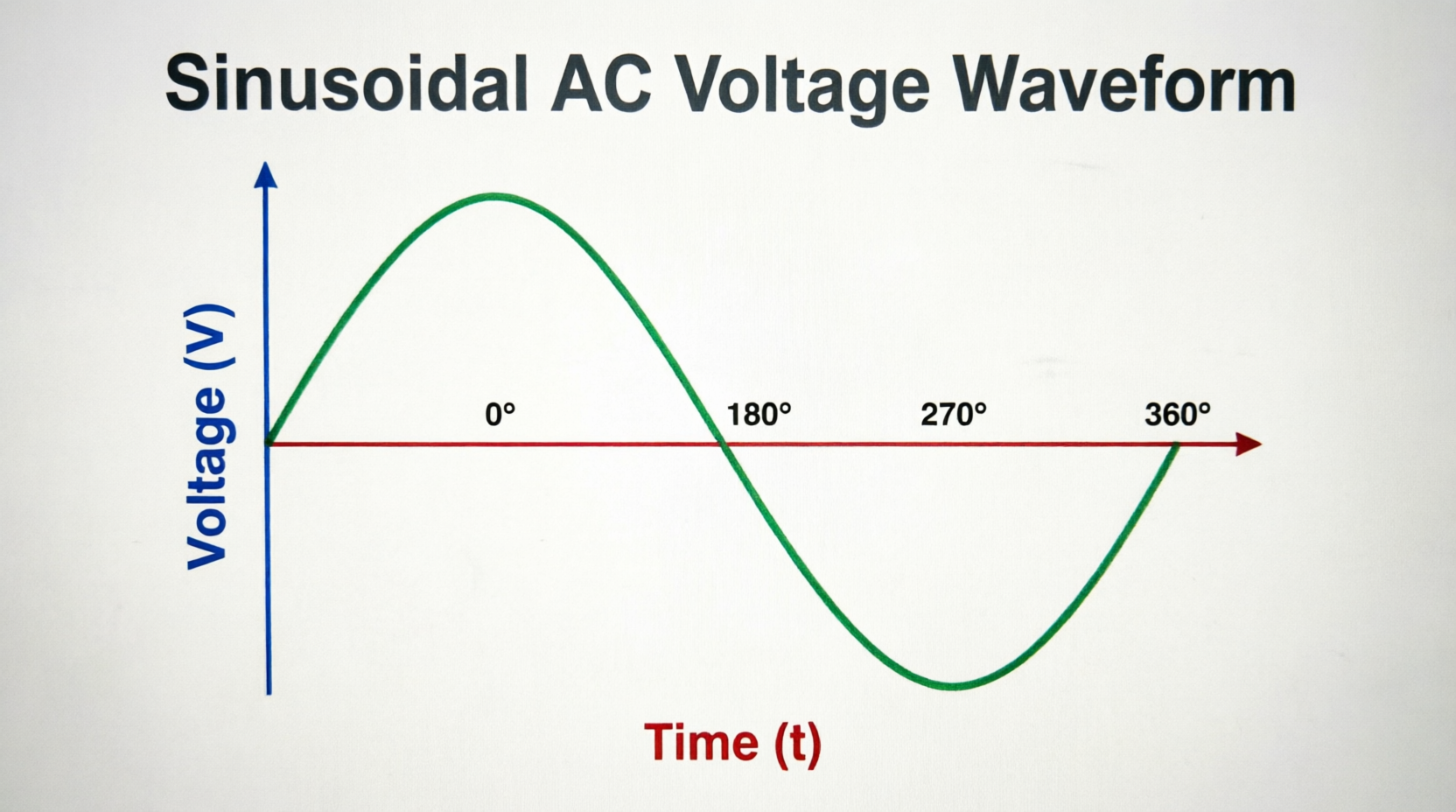
When an AC voltage is applied to a capacitor, the continuously changing voltage causes the capacitor to continuously charge and discharge. During the positive half-cycle of the AC waveform, the capacitor charges in one direction. As the voltage decreases and reverses during the negative half-cycle, the capacitor discharges and then charges in the opposite direction.
This continuous charging and discharging creates a current flow in the external circuit, even though no actual electrons pass through the dielectric material between the plates. The current appears to “flow through” the capacitor, making it behave like a frequency-dependent conductor in AC circuits.
The Current-Voltage Relationship
The current through a capacitor is proportional to the rate of change of the voltage across it, not the voltage itself. This relationship is expressed mathematically as:
i(t) = C × dv/dt
Where:
- i(t) = Instantaneous current
- C = Capacitance
- dv/dt = Rate of change of voltage with respect to time
This fundamental relationship explains why capacitors behave differently at different frequencies. At higher frequencies, the voltage changes more rapidly (larger dv/dt), resulting in larger current flow for the same voltage amplitude.
Why does current lead voltage in a capacitor?
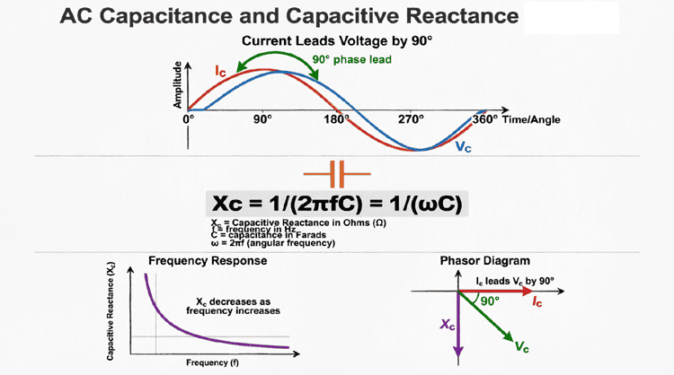
In a capacitor, current leads voltage by 90° because current flows in response to the rate of change of voltage, not the voltage itself. The maximum rate of change occurs when the voltage waveform crosses zero, causing maximum current at that point. Conversely, when voltage reaches its peak, the rate of change is zero, resulting in zero current.
Capacitive Reactance (X_C)
Definition and Formula
Capacitive reactance is the opposition that a capacitor offers to alternating current flow. Unlike resistance, which is constant regardless of frequency, capacitive reactance varies inversely with both the frequency of the AC signal and the capacitance value.
The formula for capacitive reactance is:
X_C = 1 / (2πfC)
Where:
- X_C = Capacitive reactance in ohms (Ω)
- π = Pi (approximately 3.14159)
- f = Frequency in hertz (Hz)
- C = Capacitance in farads (F)
Alternatively, using angular frequency (ω = 2πf):
X_C = 1 / (ωC)
Frequency Dependence
The inverse relationship between capacitive reactance and frequency has important practical implications:
- At Low Frequencies: When the frequency is low, the capacitive reactance is high, meaning the capacitor strongly opposes current flow. At DC (f = 0 Hz), the capacitive reactance is theoretically infinite, and the capacitor acts as an open circuit.
- At High Frequencies: When the frequency is high, the capacitive reactance is low, allowing current to flow more easily. At very high frequencies, a capacitor behaves almost like a short circuit.
This frequency-dependent behavior makes capacitors invaluable in filter circuits, where they can be used to block low frequencies while passing high frequencies (high-pass filters) or vice versa when combined with other components.
Capacitance Dependence
Capacitive reactance is also inversely proportional to capacitance:
- Larger Capacitance: A capacitor with a larger capacitance value has lower reactance at a given frequency, allowing more current to flow.
- Smaller Capacitance: A capacitor with a smaller capacitance value has higher reactance, restricting current flow.
This relationship allows engineers to select appropriate capacitor values for specific applications based on the desired reactance at the operating frequency.
The 90-Degree Phase Shift: Current Leads Voltage
Understanding the Phase Relationship
One of the most distinctive characteristics of a purely capacitive AC circuit is the phase relationship between voltage and current. In a capacitor, the current leads the voltage by 90 degrees (or equivalently, the voltage lags the current by 90 degrees).
This phase shift occurs because:
- At Zero Voltage Crossing: When the AC voltage waveform crosses zero, it is changing at its maximum rate. Since capacitor current is proportional to the rate of change of voltage (i = C·dv/dt), the current reaches its maximum value at this point.
- At Peak Voltage: When the voltage reaches its positive or negative peak, it is momentarily not changing (dv/dt = 0). Therefore, the current through the capacitor is zero at these points.
- Quarter-Cycle Shift: This relationship creates a quarter-cycle (90°) shift between the current and voltage waveforms, with the current reaching its peaks and zero crossings before the voltage does.
Visualizing the Capacitor Phase Relationship
Mathematical Representation
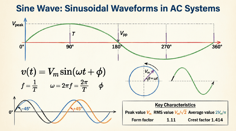
If the voltage across a capacitor is given by:
v(t) = V_m × sin(ωt)
Then the current through the capacitor is:
i(t) = I_m × sin(ωt + 90°) = I_m × cos(ωt)
Where:
- V_m = Peak voltage
- I_m = Peak current = V_m / X_C
- ω = Angular frequency (rad/s)
The +90° term in the current equation explicitly shows that the current leads the voltage by 90 degrees.
Power in a Pure Capacitive Circuit
Instantaneous and Average Power
In a purely capacitive AC circuit, the power behavior is similar to that of a purely inductive circuit but with opposite phase characteristics. The instantaneous power is the product of instantaneous voltage and current:
p(t) = v(t) × i(t)
Because voltage and current are 90 degrees out of phase, the instantaneous power waveform has a frequency that is twice the supply frequency and alternates equally between positive and negative values.
Real Power vs. Reactive Power
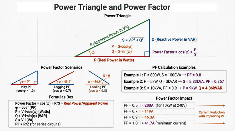
Real Power (P): In a pure capacitor, the average real power over a complete cycle is zero. This is because the energy stored in the electric field during one quarter-cycle is completely returned to the source during the next quarter-cycle. No energy is dissipated as heat (unlike in a resistor).
Reactive Power (Q_C): Although no real power is consumed, the capacitor does exchange energy with the source. This energy exchange is quantified as reactive power, measured in Volt-Amperes Reactive (VAR). For a capacitor:
Q_C = V_rms × I_rms = I_rms² × X_C = V_rms² / X_C
The reactive power for a capacitor is conventionally considered negative (Q_C < 0), indicating that it supplies reactive power to the circuit, opposite to an inductor which consumes reactive power.
Energy Storage and Release
The energy stored in a capacitor’s electric field at any instant is:
W = ½ C V²
Where:
- W = Energy in joules (J)
- C = Capacitance in farads (F)
- V = Instantaneous voltage across the capacitor
During each AC cycle:
- The capacitor charges and stores energy when the voltage magnitude increases
- The capacitor discharges and returns energy when the voltage magnitude decreases
- This continuous energy exchange creates the reactive power flow
Does a capacitor consume real power?
A pure capacitor consumes zero real power (watts). Instead, it continuously stores energy in its electric field during one part of the AC cycle and returns that energy to the source during another part. This energy exchange is measured as reactive power (VAR), which is negative for capacitors, indicating they supply reactive power to the circuit.
Combining Capacitors in AC Circuits
Capacitors in Series
When capacitors are connected in series, the total capacitance is less than any individual capacitance. The reciprocal of the total capacitance equals the sum of the reciprocals of the individual capacitances:
1/C_total = 1/C₁ + 1/C₂ + 1/C₃ + …
For two capacitors in series:
C_total = (C₁ × C₂) / (C₁ + C₂)
The total capacitive reactance of series capacitors is the sum of individual reactances:
X_C(total) = X_C1 + X_C2 + X_C3 + …
Capacitors in Parallel
When capacitors are connected in parallel, the total capacitance is the sum of the individual capacitances:
C_total = C₁ + C₂ + C₃ + …
The total capacitive reactance of parallel capacitors is calculated using the reciprocal formula:
1/X_C(total) = 1/X_C1 + 1/X_C2 + 1/X_C3 + …
For two capacitors in parallel:
X_C(total) = (X_C1 × X_C2) / (X_C1 + X_C2)
Example: Calculating Total Capacitance and Reactance
Problem: Three capacitors with values C₁ = 10 μF, C₂ = 22 μF, and C₃ = 47 μF are connected to a 120V, 60Hz AC source. Calculate the total capacitance and capacitive reactance when they are connected (a) in series and (b) in parallel.
Solution (a) – Series Connection:
1/C_total = 1/10 + 1/22 + 1/47
1/C_total = 0.1 + 0.0455 + 0.0213 = 0.1668 μF⁻¹
C_total = 1/0.1668 = 5.99 μF
X_C(total) = 1/(2πfC) = 1/(2π × 60 × 5.99×10⁻⁶)
X_C(total) = 1/(0.002258) = 442.8 Ω
Solution (b) – Parallel Connection:
C_total = 10 + 22 + 47 = 79 μF
X_C(total) = 1/(2π × 60 × 79×10⁻⁶)
X_C(total) = 1/(0.02978) = 33.6 Ω
This example demonstrates how series connection reduces total capacitance (increasing reactance), while parallel connection increases total capacitance (decreasing reactance).
Practical Applications of Capacitive Reactance
1. Power Factor Correction
Capacitors are widely used in industrial and commercial facilities to correct power factor. Since inductive loads (motors, transformers) cause current to lag voltage, capacitors (which cause current to lead voltage) can be added to cancel out the inductive reactive power. This improves the power factor, reduces current draw, and lowers electricity costs.
2. AC Coupling and DC Blocking
Capacitors are used to couple AC signals between amplifier stages while blocking DC components. This is possible because capacitors have high reactance at DC (blocking it) but low reactance at AC signal frequencies (passing it).
3. Filter Circuits
Capacitors are essential components in filter circuits:
- High-Pass Filters: Capacitors in series pass high frequencies while blocking low frequencies
- Low-Pass Filters: Capacitors in parallel shunt high frequencies to ground while passing low frequencies
- Band-Pass Filters: Combinations of capacitors and inductors select specific frequency ranges
4. Timing and Waveform Shaping
In combination with resistors, capacitors create RC time constants used in timing circuits, oscillators, and waveform shaping applications. The charging and discharging characteristics of capacitors are exploited in these applications.
5. Motor Starting and Running
Single-phase AC motors use capacitors to create a phase shift that produces a rotating magnetic field necessary for starting and running. Start capacitors provide high torque during startup, while run capacitors improve efficiency during operation.
6. Energy Storage and Pulsed Power
Capacitors can store electrical energy and release it quickly, making them ideal for applications requiring high peak power, such as camera flashes, defibrillators, and pulsed laser systems.
Real-World Capacitor Considerations
Equivalent Series Resistance (ESR)
Real capacitors are not perfect. They have a small amount of internal resistance called Equivalent Series Resistance (ESR), which causes some power dissipation as heat. Low ESR is desirable in most applications, especially in power supply filtering and high-frequency circuits.
Voltage Rating
Every capacitor has a maximum voltage rating that should not be exceeded. Operating a capacitor above its rated voltage can cause dielectric breakdown, leading to capacitor failure, potentially with catastrophic results (explosion or fire in electrolytic capacitors).
Frequency Limitations
Capacitors have practical frequency limitations. At very high frequencies, parasitic inductance and resistance become significant, causing the capacitor to deviate from ideal behavior. Different capacitor types (ceramic, electrolytic, film) have different frequency characteristics.
Temperature Coefficient
Capacitance values can change with temperature. Some applications require capacitors with stable temperature coefficients, while others may use capacitors with specific temperature-dependent characteristics.
Leakage Current
Real capacitors have a small amount of DC leakage current through the dielectric. This is particularly important in electrolytic capacitors and in applications requiring long-term charge storage.
Measurement and Testing of Capacitors
Capacitance Measurement
Capacitance can be measured using:
- LCR Meters: Dedicated instruments that measure capacitance, inductance, and resistance
- Multimeters with Capacitance Function: Many modern digital multimeters include capacitance measurement
- Oscilloscope Methods: In Oscilloscope use RC time constant measurements with known resistors
ESR Measurement
ESR meters are specialized instruments that measure the equivalent series resistance of capacitors, particularly useful for testing electrolytic capacitors in power supplies.
Leakage Current Testing
High-voltage capacitors, especially in power applications, should be tested for leakage current to ensure safe operation.
Summary and Conclusion
AC capacitance and capacitive reactance represent fundamental concepts in electrical engineering with wide-ranging practical applications. Unlike resistors that simply dissipate energy, capacitors store and release energy in electric fields, creating unique behaviors in AC circuits.
Key points to remember:
- Capacitive Reactance Formula: X_C = 1/(2πfC) – reactance decreases with increasing frequency and capacitance
- Phase Relationship: In a pure capacitor, current leads voltage by 90°, opposite to the lag in inductors
- Power Characteristics: Pure capacitors consume zero real power but exchange reactive power with the source (negative VAR)
- Frequency Behavior: Capacitors block DC (infinite reactance at f=0) and pass AC (decreasing reactance with increasing frequency)
- Combination Rules: Series capacitors reduce total capacitance; parallel capacitors increase total capacitance
- Practical Applications: Power factor correction, filtering, coupling, timing circuits, motor operation, and energy storage
Understanding capacitive reactance and capacitor behavior in AC circuits is essential for designing and analyzing filters, power systems, signal processing circuits, and countless other electrical and electronic applications. The ability of capacitors to store energy, block DC while passing AC, and create phase shifts makes them indispensable components in modern electrical engineering.
As you continue your study of AC circuits, the principles of capacitance will combine with resistance and inductance to create complex behaviors in RLC circuits, resonance phenomena, and advanced filter designs. Mastering these fundamentals provides the foundation for understanding more sophisticated circuit analysis and design techniques.