Power Triangle and Power Factor
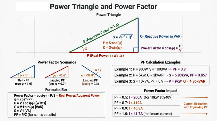
Power Triangle and Power Factor: The Complete Guide to AC Efficiency
Introduction to the Power Triangle and Power Factor
If you ask an electrical engineer to explain AC power to a layperson, they will almost inevitably reach for a glass of beer. This famous “beer analogy” perfectly encapsulates the concepts of the Power Triangle and Power Factor.
Imagine a mug of beer. The liquid beer itself represents Real Power (P)—the useful part that actually quenches your thirst (performs useful work). The frothy foam on top represents Reactive Power (Q)—it doesn’t quench your thirst, but it’s necessary to deliver the beer and takes up space in the mug. The total contents of the mug (beer + foam) represent Apparent Power (S).
The Power Factor (PF) is the ratio of the liquid beer to the total mug contents. You want as much beer and as little foam as possible. A high power factor means your electrical system is highly efficient, delivering maximum useful power with minimal wasted “foam” (reactive power).
The Power in AC Circuits introduced the basic components of AC power, but this tutorial dives deep into the geometric relationships that govern them. We will explore the three similar triangles of AC circuits, the nuances of lagging versus leading power factor, the impact of harmonics, and the precise mathematics of power factor correction.
What is the Power Triangle?
The Power Triangle is a right-angled geometric representation of AC power. The horizontal base represents Real Power (P, in Watts), the vertical height represents Reactive Power (Q, in VAR), and the hypotenuse represents Apparent Power (S, in VA). The angle between P and S is the phase angle ($\theta$), and its cosine is the Power Factor.
The Three Similar Triangles of AC Circuits
One of the most elegant concepts in AC circuit theory is that the impedance, voltage, and power relationships all form similar right-angled triangles. Understanding this geometric link is the key to mastering AC analysis.
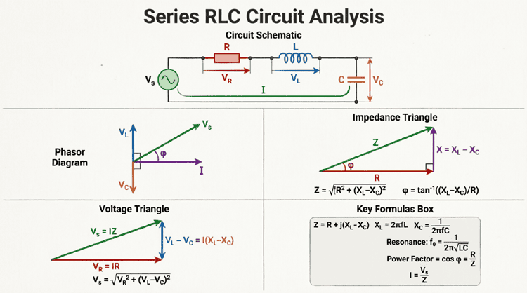
1. The Impedance Triangle
The foundation of all AC triangles is the Impedance Triangle, which we explored in earlier articles. It consists of:
- Base: Resistance ($R$)
- Height: Net Reactance ($X = X_L – X_C$)
- Hypotenuse: Impedance ($Z$)
- Angle: Phase angle ($\theta$)
2. The Voltage Triangle
If you multiply every side of the Impedance Triangle by the circuit current ($I$), you get the Voltage Triangle (since $V = I \times Z$):
- Base: Resistive Voltage Drop ($V_R = I \times R$)
- Height: Reactive Voltage Drop ($V_X = I \times X$)
- Hypotenuse: Total Source Voltage ($V_S = I \times Z$)
- Angle: Phase angle ($\theta$)
3. The Power Triangle
If you multiply every side of the Voltage Triangle by the current ($I$) again, you get the Power Triangle (since $P = V \times I$):
- Base: Real Power ($P = I \times V_R = I^2R$)
- Height: Reactive Power ($Q = I \times V_X = I^2X$)
- Hypotenuse: Apparent Power ($S = I \times V_S = I^2Z$)
- Angle: Phase angle ($\theta$)
Because they are all derived by simple scalar multiplication, all three triangles share the exact same phase angle ($\theta$) and the same trigonometric ratios. This means if you know the values for one triangle, you can easily calculate the others.
Why are the Impedance, Voltage, and Power triangles similar?
They are similar because they are mathematically proportional. The Voltage Triangle is the Impedance Triangle multiplied by current ($I$). The Power Triangle is the Voltage Triangle multiplied by current ($I$). Therefore, they all share the exact same phase angle ($\theta$) and geometric shape.
Deep Dive into the Power Triangle
Let’s dissect the Power Triangle and understand the physical meaning of its components and geometry.
The Components
- Real Power (P) – The Base: Measured in Watts (W). This is the power that does actual work. It is always positive for passive loads.
- Reactive Power (Q) – The Height: Measured in Volt-Amperes Reactive (VAR). This is the power that oscillates between the source and the load. It can be positive (inductive) or negative (capacitive).
- Apparent Power (S) – The Hypotenuse: Measured in Volt-Amperes (VA). This is the total power the source must supply. It is always a positive magnitude.
The Phase Angle ($\theta$)
The angle $\theta$ is the phase difference between the source voltage and the total current.
- If the circuit is inductive (current lags voltage), $Q$ is positive, and the triangle points upward.
- If the circuit is capacitive (current leads voltage), $Q$ is negative, and the triangle points downward.
Trigonometric Relationships
The power triangle allows us to use basic trigonometry to solve for unknown power values:
- Pythagorean Theorem: $S = \sqrt{P^2 + Q^2}$
- Cosine (Power Factor): $\cos(\theta) = \frac{P}{S}$
- Sine (Reactive Factor): $\sin(\theta) = \frac{Q}{S}$
- Tangent: $\tan(\theta) = \frac{Q}{P}$
Understanding Power Factor (PF)
Power Factor is defined as the ratio of Real Power to Apparent Power. It is a dimensionless number between 0 and 1 (or 0% and 100%) that indicates the efficiency of power usage.
$PF = \frac{P}{S} = \cos(\theta)$
Lagging vs. Leading Power Factor
In AC systems, we must specify not just the magnitude of the power factor, but its direction (whether the current is lagging or leading the voltage).
1. Lagging Power Factor (Inductive)
- Cause: Inductive loads like electric motors, transformers, and solenoids.
- Behavior: Current lags behind voltage.
- Reactive Power: $Q$ is positive (consumes VARs).
- Triangle Orientation: Points upward.
- Prevalence: This is the most common state in industrial and commercial facilities.
2. Leading Power Factor (Capacitive)
- Cause: Capacitive loads like capacitor banks, long underground cables, or over-corrected systems.
- Behavior: Current leads voltage.
- Reactive Power: $Q$ is negative (supplies VARs).
- Triangle Orientation: Points downward.
3. Unity Power Factor (Resistive)
- Cause: Purely resistive loads (heaters, incandescent bulbs) or a perfectly corrected system.
- Behavior: Current and voltage are perfectly in phase ($\theta = 0^\circ$).
- Reactive Power: $Q = 0$.
- Triangle Orientation: Collapses into a straight horizontal line ($S = P$).
- Ideal State: Represents 100% efficiency.
What is the difference between lagging and leading power factor?
A lagging power factor means current lags voltage, caused by inductive loads (motors), and consumes reactive power (+Q). A leading power factor means current leads voltage, caused by capacitive loads (capacitors), and supplies reactive power (-Q). Most industrial facilities have a lagging power factor.
Displacement Power Factor vs. True Power Factor
In modern electrical systems, it is crucial to distinguish between two types of power factor, especially when non-linear loads (like computers and VFDs) are present.
Displacement Power Factor ($PF_{disp}$)
This is the traditional power factor we have been discussing. It only considers the phase shift ($\theta$) between the fundamental (60 Hz or 50 Hz) voltage and current waveforms.
$PF_{disp} = \cos(\theta)$
Distortion Power Factor ($PF_{dist}$)
Non-linear loads draw current in abrupt pulses, creating harmonic distortion. Even if the fundamental voltage and current are perfectly in phase ($\theta = 0$), the presence of harmonics reduces the efficiency of the system. Distortion power factor accounts for this harmonic content.
$PF_{dist} = \frac{1}{\sqrt{1 + THD_I^2}}$
(Where $THD_I$ is the Total Harmonic Distortion of the current).
True Power Factor ($PF_{true}$)
The actual, overall power factor of the system is the product of the two:
$PF_{true} = PF_{disp} \times PF_{dist}$
If a facility has a displacement PF of 0.95 but a high harmonic distortion ($THD_I = 30\%$), the true power factor drops to roughly 0.86. This is why simply adding capacitors (which only fix displacement PF) will not solve power factor issues caused by harmonics.
The Cost of Low Power Factor
Why do utility companies and facility managers care so much about the power triangle? Because a low power factor has severe economic and physical consequences.
1. Increased Current and $I^2R$ Losses
To deliver a specific amount of Real Power ($P$), the current required is inversely proportional to the power factor:
$I = \frac{P}{V \times PF}$
If PF drops from 1.0 to 0.7, the current increases by 43%. Since power losses in conductors are proportional to the square of the current ($I^2R$), the losses increase by over 100%!
2. Oversized Equipment
Transformers, generators, switchgear, and cables must be sized based on Apparent Power (kVA) or total current, not just Real Power (kW). A low PF forces you to buy larger, more expensive equipment to handle the excess “foam” (reactive power).
3. Voltage Drop
The increased current drawn by a low power factor causes a larger voltage drop across the distribution lines ($V_{drop} = I \times Z_{line}$). This can lead to poor voltage regulation, causing motors to overheat and lights to dim.
4. Utility Penalties
Most industrial utility contracts include a power factor penalty. If the facility’s average PF drops below a threshold (usually 0.90 or 0.95 lagging), the utility charges a premium or bills the customer based on kVA demand rather than kW demand.
Power Factor Correction (PFC)
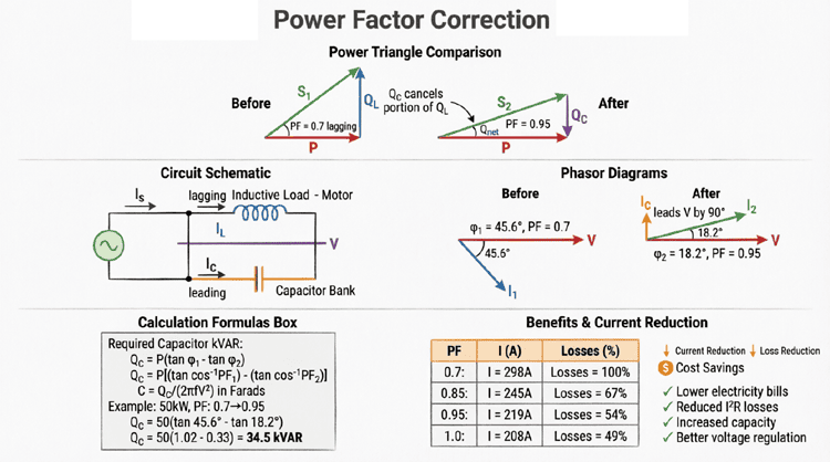
Power Factor Correction is the process of improving the power factor of a circuit, bringing it closer to unity (1.0). Since most industrial loads are inductive (lagging), PFC is typically achieved by adding capacitors in parallel with the load.
How Capacitors Correct Power Factor
Capacitors generate leading reactive power (-Q). When placed in parallel with an inductive load that consumes lagging reactive power (+Q), the capacitor’s reactive power cancels out a portion of the inductor’s reactive power.
This reduces the net reactive power ($Q_{net}$) drawn from the utility, which shrinks the height of the Power Triangle, reduces the hypotenuse (Apparent Power), and decreases the phase angle ($\theta$), thereby increasing the Power Factor.
Calculating Power Factor Correction
To size a capacitor bank for power factor correction, you need to know the initial real power ($P$), the initial power factor ($PF_1$), and the target power factor ($PF_2$).
Step 1: Find the initial and target phase angles.
$\theta_1 = \arccos(PF_1)$
$\theta_2 = \arccos(PF_2)$
Step 2: Calculate the required reactive power compensation ($Q_c$).
The capacitor must supply the difference in reactive power:
$Q_c = P \times (\tan(\theta_1) – \tan(\theta_2))$
Note: Never correct to exactly 1.0 (unity). Over-correction creates a leading power factor, which can cause voltage swells and resonance issues with system inductance. A target of 0.95 to 0.98 lagging is standard.
Practical Examples and Calculations
Example 1: Analyzing the Power Triangle
Problem: An industrial motor draws 50 kW of real power and 35 kVAR of reactive power from the grid. Calculate the apparent power, the phase angle, and the power factor.
Solution:
Given:
- $P = 50 \text{ kW}$
- $Q = 35 \text{ kVAR}$ (inductive, so positive)
Calculate Apparent Power (S):
$S = \sqrt{P^2 + Q^2}$
$S = \sqrt{50^2 + 35^2}$
$S = \sqrt{2500 + 1225} = \sqrt{3725}$
$S \approx 61.03 \text{ kVA}$
Calculate Phase Angle ($\theta$):
$\theta = \arctan\left(\frac{Q}{P}\right)$
$\theta = \arctan\left(\frac{35}{50}\right) = \arctan(0.7)$
$\theta \approx 34.99^\circ$
Calculate Power Factor (PF):
$PF = \cos(\theta) = \cos(34.99^\circ)$
$PF \approx 0.819$ (or 81.9% Lagging)
Alternatively: $PF = P / S = 50 / 61.03 = 0.819$
Example 2: Sizing a Capacitor Bank for PFC
Problem: The motor in Example 1 (50 kW, PF = 0.819 lagging) needs its power factor improved to 0.95 lagging to avoid utility penalties. Calculate the required capacitor kVAR.
Solution:
Given:
- $P = 50 \text{ kW}$
- $PF_1 = 0.819$
- $PF_2 = 0.95$
Step 1: Find Phase Angles
$\theta_1 = \arccos(0.819) \approx 35.0^\circ$
$\theta_2 = \arccos(0.95) \approx 18.19^\circ$
Step 2: Find Tangents
$\tan(35.0^\circ) \approx 0.700$
$\tan(18.19^\circ) \approx 0.329$
Step 3: Calculate Required Capacitor kVAR ($Q_c$)
$Q_c = P \times (\tan(\theta_1) – \tan(\theta_2))$
$Q_c = 50 \times (0.700 – 0.329)$
$Q_c = 50 \times 0.371$
$Q_c = 18.55 \text{ kVAR}$
Result: Installing an 18.55 kVAR capacitor bank in parallel with the motor will reduce the reactive power drawn from the grid from 35 kVAR to 16.45 kVAR, improving the power factor from 0.82 to 0.95 and reducing the apparent power demand from 61 kVA to 52.6 kVA.
Summary and Conclusion
The Power Triangle and Power Factor are the ultimate metrics of AC electrical efficiency. By visualizing power as a geometric triangle, engineers can easily calculate real, reactive, and apparent power, and understand the profound impact of phase shifts on electrical systems.
Key takeaways from this guide include:
- The Three Similar Triangles: Impedance, Voltage, and Power triangles are geometrically similar, sharing the exact same phase angle ($\theta$).
- Power Factor Definition: $PF = \cos(\theta) = P/S$. It measures how effectively apparent power is converted into useful real power.
- Lagging vs. Leading: Inductive loads cause lagging PF (consuming VARs), while capacitive loads cause leading PF (supplying VARs).
- True vs. Displacement PF: In modern systems with harmonics, True Power Factor accounts for both phase displacement and waveform distortion.
- The Cost of Low PF: Low power factor increases current, causes $I^2R$ losses, requires oversized equipment, and incurs utility penalties.
- Power Factor Correction: Adding parallel capacitors cancels inductive reactive power, shrinking the Power Triangle and improving system efficiency. Target PF is usually 0.95 lagging.
Mastering the Power Triangle allows you to look at a complex AC circuit and instantly understand its efficiency, its reactive demands, and how to optimize it. Whether you are sizing a transformer for a new factory, troubleshooting voltage drops in a commercial building, or designing a capacitor bank for grid stability, the principles of the power triangle and power factor are your most essential analytical tools.