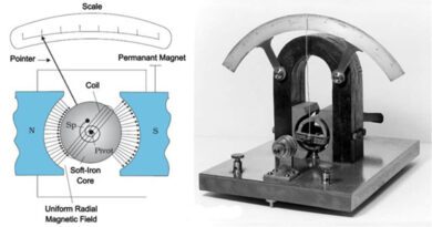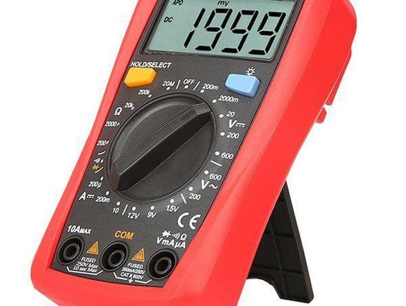
DIGITAL METERS
Digital meter measurements are displayed in discrete numbers. They are available to measure AC and DC voltages, AC and DC currents and resistance.
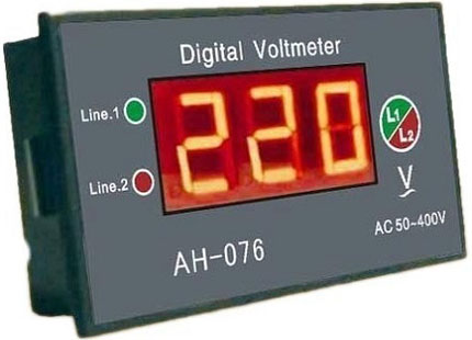
DIGITAL VOLTMETER (DVM)
Most digital instruments are made around a digital voltmeter (DVM). Once a basic DVM circuit is built, then with proper transducers, a wide range of physical parameters such as current and resistance can be measured and displayed.
Construction of DVM
Construction of a digital voltmeter consist of three parts. The function of three blocks is discussed below.
1. Signal Convertor:
The signal convertor block converts the measured function of voltage, current, resistance etc. into a form which the analog to digital convertor block can deal with. This form is typically 200 mVDc or 2 VDc.
The resistive divider chain attenuates the measured voltage value in switched steps, so that out put voltage is within the input range of analog to digital convertor. AC voltage measurement is usually done with the use of a circuit called a True RMS Convertor.
Switching between ranges, when a measurement is made usually a manual operation. but some modern digital millimeters have an auto-range facility, which electrically senses the level of the measured signal and selects the appropriate range for display.
2. Analog-to-Digital Convertor:
The principle of conversion of analog signal into a digital signal is very easy. The analog signal is merely sampled, that is, a measurement of the signal value is taken at regular intervals and each sample is presented in a binary digital way. Two convertors are popular.
i. Dual Slop Convertor:
The input of the integrator is electronically switched between a reference voltage Vref and the voltage to be converted Vin. By integrating the analog voltage for a fixed period of time t1, as the integrator output voltage ramps up from zero then counting the clock pulses for the variable time t2 which the integrator takes for its output voltage to ramp back down to zero. In this way a very accurate analog to digital conversion ca be made because the time t2 is proportional to the analog voltage.
ii. Successive Approximation Convertor:
The successive approximation convertor is an example of an analog-to-digital convertor which uses a digital-to-analog convertor within itself. Digital output of the convertor is reconverted back to analog by the digital-to-analog convertor, then compared with the analog input voltage by a convertor. The voltage gets closer to that of output voltage with each comparison and approximation.
3. Display:
Mostly liquid crystal display (LCD) are used. They have a low current consumption which is only in microamperes. But large digital meters may use light emitting diodes (LED), vacuum fluorescent displays, etc.
DIGITAL OHMMETER
A digital voltmeter (DVM) can be easily converted into a digital ohmmeter. One of the commonly used technique to measure DC resistance with a digital meter is to pass a constant current through the unknown resistance and measure the resulting voltage drop.
For example, if the basic DVM were placed on the 1-V range and a constant current surce of 1 mA were used, the meter would have a resistance range of 0 to 100V.
DIGITAL AMMETER
Current may be displayed on a digital meter by measuring the voltage which the current creates across a known internal resistance.
THE DIGITAL MULTIMETER
The digital multimeter (DMM) is a signal DVM circuit and the display shares between the three basic functions of voltmeter, ammeter and ohmmeter.
Construction:
The actual circuits for measuring AC and DC voltage, AC and DC current and resistance are the same as that of digital voltmeter, ammeter and ohmmeter. They have a simple DVM section combined with suitable current-to-voltage and resistance-to-voltage transducer circuits.
- AC, DC and ohm selector switch
- AC, DC and ohm convertors
- Analog to digital convertor
- Digital display
- Optional digital interface is also shown to interface to output to data loggers or computers.
Some Useful Features:
1. Diode Test:
This feature is represented by a diode symbol. A good forward biased junction reads 0.7V while a good reversed-biased junction will read “OL” for overload. This is also used to check the base-emitter or base-collector junctions.
2. Touch Hold:
The feature permits the meter to capture and hold a reading so that user may remove leads from the circuit under test before reading the display.
3. Peak Hold:
This feature permits the meter to store and hold the peak measured value until cleared by the user.
4. Bar graph display:
Some digital meters also have a bar graph feature on the display giving the operator some of the benefits of the analog display.
Advantages and Disadvantages of Digital Meters
Advantages
- They reduce human error.
- They eliminate error due to parallex.
- They have a greatly increased resolution on a given meter range,
- Some models have automatic polarity and range altering features that reduce both operator skill level requirements and the possibility of damage due to overload.
Disadvantages
- They have a sampling rate of 1 to 5 readings per second which is very low. So sudden peaks or changes in the measured parameter may not be displayed.
- The direction and relative magnitude of a signal change during an adjustments may be more readily apparent using an analog meter then digital meter.