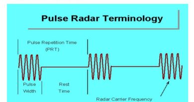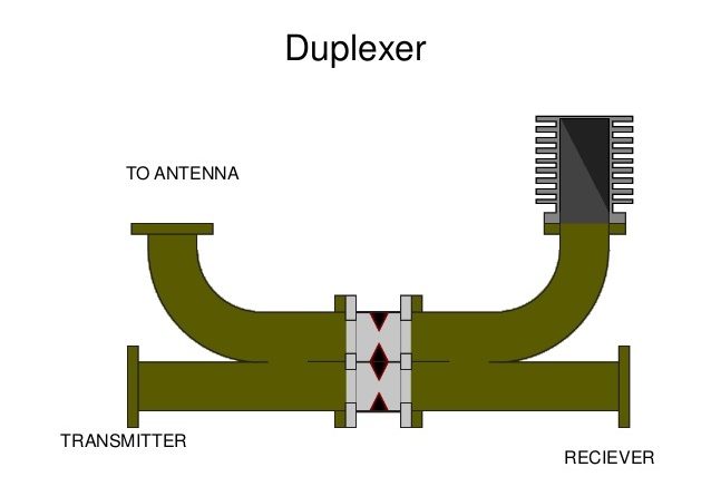
Duplexer
The Duplexer permits the same antenna to be used for both transmission and reception. It utilizes fast-acting radio frequency switches called the TR (Trans receive) switches and ATR (Anti Trans receive) switch. These switches are operated by energy from the transmitted pulse and these switches protect the sensitive and delicate radar receiver from the damaging effect of high energy pulses from the transmitter. A typical TR switch for use in co-axial circuits. It consists of a resonant cavity associated with a special cold cathode tube. The tube itself contains inert gas at low pressure. High energy transmitter pulse causes ionization across the narrow internal gap, thereby destroying the resonance in the TR switch. The switch then acts almost as a short circuit and permits little transmission of energy from input to output line. The discharge takes very little energy to maintain. On the other hand, when the gas tube is inoperative, the cavity resonance enables energy to be transferred freely through the resonant cavity.
An ATR of Anti – TR switch is a TR switch without the output lead. The Anti – TR switch functions as either short-circuited load impedance or as open – circuited load impedance. A typical duplexer system for both co-axial line system or two wire line system. When the RF pulse travels from the transmitter to the antenna, both the TR and ART switches ionizes and become almost short circuits. The equivalent short circuit. The branch lines cd and ab now have no effect upon the transmitter operation, because, being an odd number of quarter wavelength long and short-circuited at the ends a, and b, respectively. They represent on extremely high impedance shunting the transmission line. At the same time, since the TR switch approximates a short circuit at b, it prevents what little energy goes reach b from going on to the receiver and so serves the highly important purpose of isolating the receiver. After the end of the transmitter pulse, both TR and ATR switches de-ionize rapidly and become open circuited. The open circuit at d places very low impedance across the line at c, which in turn causes the impedance looking toward the transmitter to be very high. As a consequence, substantially all of the echo energy coming in from the receiving antenna and reaching a travels toward the receiver, and the transmitter is effectively disconnected.
Radar Functions
No single radar system has yet been designed that can perform all of the many radar functions required by the military. Some of the newer systems combine several functions that formerly required individual radar systems, but no single system can fulfill all the requirements of modern warfare. As a result, modern warships, aircraft, and shore stations usually have several radar systems, each performing a different function. One radar system, called SEARCH RADAR, is designed to continuously scan a volume of space to provide initial detection of all targets. Search radar is almost always used to detect and determine the position of new targets for later use by TRACK RADAR. Track radar provides continuous range, bearing, and elevation data on one or more targets. Most of the radar systems used by the military are in one of these two categories, though the individual radar systems vary in design and capability.
Search Radar
Search radar, as previously mentioned, continuously scans a volume of space and provides initial detection of all targets within that space. Search radar systems are further divided into specific types, according to the type of object they are designed to detect. For example, surface-search, air-search, and height-finding radars are all types of search radar.
Surface-Search Radar
A surface-search radar system has two primary functions:
(1) The detection and determination of accurate ranges and bearings of surface objects and low-flying aircraft and
(2) The maintenance of a 360-degree search pattern for all objects within line-of-sight distance from the radar antenna. The maximum range ability of surface-search radar is primarily limited by the radar horizon; therefore, higher frequencies are used to permit maximum reflection from small, reflecting areas, such as ship masthead structures and the periscopes of submarines. Narrow pulse widths are used to permit a high degree of range resolution at short ranges and to achieve greater range accuracy. High pulse-repetition rates are used to permit a maximum definition of detected objects. Medium peak power can be used to permit the detection of small objects at line-of-sight distances. Wide vertical-beam widths permit compensation for the pitch and roll of own ship and detection of low flying aircraft. Narrow horizontal beam widths permit accurate bearing determination and good bearing resolution. For example, a common shipboard surface-search radar has the following design specifications:
Transmitter frequency 5,450-5,825 MHz
Pulse width .25 or 1.3 microseconds
Pulse-repetition rate between 625 and 650 pulses per second
Peak power between 190 and 285 kW
Vertical beam width between 12 and 16 degrees
Horizontal beam width 1.5 degrees
Surface-search radar is used to detect the presence of surface craft and low flying aircraft and to determine. their presence. Shipboard surface-search radar provides this type of information as an input to the weapons systems to assist in the engagement of hostile targets by fire-control radar. Shipboards surface-search radar is also used extensively as a navigational aid in coastal waters and in poor weather conditions. A typical surface-search radar antenna.