Tracking Radar
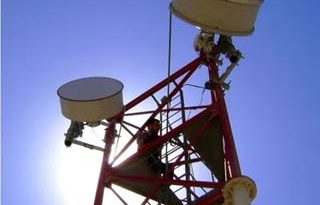
Radar that provides continuous positional data on a target is called tracking radar. Most tracking radar systems used by the military are also fire-control radar; the two names are often used interchangeably. Fire-control tracking radar systems usually produce a very narrow, circular beam. Fire-control radar must be directed to the general location of the desired target because of the narrow-beam pattern. This is called the DESIGNATION phase of equipment operation. Once in the general vicinity of the target, the radar system switches to the ACQUISITION phase of operation. During acquisition, the radar system searches a small volume of pace in a prearranged pattern until the target is located. When the target is located, the radar system enters the TRACK phase of operation. Using one of several possible scanning techniques, the radar system automatically follows all target motions. The radar system is said to be locked on to the target during the track phase. The three sequential phases of operation are often referred to as MODES and are common to the target-processing sequence of most fire-control radars. Typical fire-control radar characteristics include a very high prf, a very narrow pulse width, and a very narrow beam width. These characteristics, while providing extreme accuracy, limit the range and make initial target detection difficult. A typical fire-control radar antenna. In this (example the antenna used to produce a narrow beam is covered by .1 protective radome.
Radar Receiver
A simple block diagram of a radar receiver based on the super heterodyne principle. The echo signal enters the system via the antenna and passes through the duplexer and is amplified by the low-noise RF amplifier. When the external noise is neglected. The noise generated by the input stage of the receiver determines the receiver, sensitivity. The input stage is RF amplifier but in many practical radar receivers, the RF amplifier is dispensed with and the mixer acts as the first stage. The function of the mixer stage or first detector is to translate the RF frequency to a lower intermediate frequency (IF) usually 30 or 60 MHz, this is accomplished by heterodyning the RF signal with a local oscillator in a non linear element (mixer) and extracting the signal component at the difference frequency. The frequency is translated to IF where the necessary gain is easier to obtain than at RF. It is also easier to synthesize the response function (or band-pass characteristic) of the receiver in the IF stage. The second detector, which is either a vacuum tube or crystal oscillator, extracts the video modulation from the carrier.
The modulation is amplified in the video stage to a level enough to operate the indicator or display device.
The AFC system normally employed to keep the receiver in tune with the transmitter is known as a difference frequency system. A portion of the transmitter signal is coupled into the AFC mixer and is heterodyne with the local oscillator, If the transmitter and receiver are correctly in tune. The difference frequency will be at correct IF. If the receiver is not tune with the transmitter the difference frequency will not be corrected. Any deviation from the correct IF is detected by the frequency discriminator, which generates an error voltage whose magnitude is proportional to the deviation from the correct IF, and whose sign determines the direction of the error, the error voltage corrects the frequency of the local oscillator common to both the receiver mixer and the AFC mixer.
MTI (Moving Target Indication)
The Moving Target Indication (MTI) radar system very effectively handles moving targets such as aircraft and in capable of measuring their range and radial velocity component in the presence of strong cutter due to stationary and even slow moving undesired objects such as buildings, clouds, rain etc. It is again based on the Doppler shift imparted to the transmitter signal by the moving target to determine the target’s radial velocity component. The range, of course, is measured from the time lapse between the transmit signal and the received echo. The Doppler shift is not measured exactly in the same way as it is in case of a CW radar where the process is more or less straight forward. An MTI, being a pulse system, relies on the phase difference between the transmitted signal and the corresponding echo to compute the Doppler this phase difference for successive transmit pulses of RF energy and their corresponding echoes changes in case of moving targets at a rate equal to the Doppler frequency shift. The difference however remains the same in case of stationary targets and changes at a very small rate in case of slow moving targets so as to be easily distinguishable from the phase difference information produced by relatively much faster desired targets. The principle of operation of echo signal processing.
Each echo from a given range gate is subtracted coherently from a delayed version of the previous echo from the range gate. If the target is stationary, both echoes would produce the same phase difference and there would be complete cancellation provided. The noise is absent. If the echo has changed phase slightly due to target motion, the cancellation would be incomplete. For a target in uniform motion, there would be a constant change in phase from pulse to pulse and there is no cancellation. As is clear from the above description, there is a need to maintain phase coherence because it is in the phase difference between the transmit signal and received echo for successive pulses where the target’s Doppler information resides. Based on the manner in which this phase coherence is ensured, there are two commonly used MTI configurations. These are coherent MTI and COHO – STALO type MTI. The later is basically a coherent-on-receive system. The block schematic arrangement of a coherent MTI system. Here, the transmitter is a power amplifier with its RF source controlled by a crystal reference. Both the local oscillator as well reference oscillator frequencies are synthesized from a stable reference. The transmitted frequency is the sum of the two produced by Mixer-1.
The reference oscillator output is also at the receiver intermediate frequency (IF). The received signal is routed to Mixer-2 whose other input is from the local oscillator. The mixer output at the receiver IF, which is same as reference oscillator frequency, is fed to the phase sensitive detector where it is phase sensitively detected. The output is fed to the signal processor section.
In the COHO-STALO system, the transmitter is a power. Oscillator, usually a magnetron oscillator. In this case, the receiver has an extremely stable local oscillator called STALO. The Sample of the transmitted RF output at low levels is mixed with STALO output and locking pulse. Thus generated then triggers another oscillator called COHO whose output becomes the coherent reference. It is clear that it is different output of Mixer-1 here that triggers the COHO. Rest of the system is self explanatory.