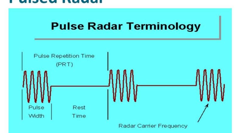
Pulsed Radar
To transmit the high frequency waves in bursts or “pulses”, and to measure the time interval between transmitting the pulse and receiving the echo. This is known as pulsed radar. Now these blocks are explained below.
Timer
The timer, which is also called the trigger generator or the synchronizer, generates a series of narrow timing, or trigger, pulses at the pulse repetion frequency. These timing pulses turn on the modulator, which pulses the transmitter. The indicator is also synchronized to the timer.
Modulator
The modulator must be capable of switching the high-power transmitter. Although both timer and modulator are switches, the only difference lies into their design considerations.
Transmitter
This consists of a radio-frequency oscillator, which is controlled by a modulator (pulses) in such a way as to produce periodic pulses of high power but of short duration.
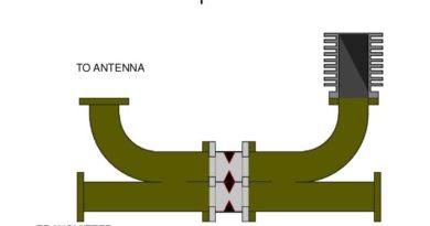
Duplexer
The TR and ATR are together called the duplexer. This controls the transmitting and receiving operations permitting the use of only one antenna for both transmitting and receiving purposes. During the pulse interval, this duplexer connects the transmitter to the antenna and isolates the sensitive receiver from the damaging effects of high power transmitting pulses. In the interval between the pulses, during which the reflected energy is being received, the duplexer connects the antenna to the receiver.
Antenna
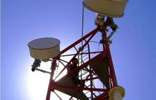
The output of the transmitter is fed to the antenna, which radiates it efficiently in the desired direction. The antenna system is highly directional and is usually capable of rotating in azimuth or in vertical planes or both and is able to direct the beam as desired.
Receiver
The radar receiver is usually of the super-heterodyne type. The RF amplifier shown as the first stage of the super-heterodyne might be a low noise parametric amplifier, a traveling wave tube, or a maser. Many radar receivers do not have an RF amplifier and use the mixer as the first stage, or front end. The mixer and local oscillator (LO) convert the RF signal to an intermediate frequency (IF) since it is easier to build high gain narrow band amplifiers at the lower frequencies. A typical IF amplifier might have a center frequency of 30 or 60 MHz and a bandwidth of 1 or 2 MHz. A reflex Klystron is commonly employed as the local oscillator. The RF pulse modulation is extracted by the detector and amplified by the video amplifier to a level where it can operate the indicator, usually a cathode-ray-tube (CRT). Timing signals are also applied to the indicator.
Synchronizers
The synchronizer is often referred to as the “heart” of the radar system because it controls and provides timing for the operation of the entire system. Other names for the synchronizer are the TIMER and the KEYER. We will use the term synchronizer in our discussion. Synchronizer Function The specific function of the synchronizer is to produce TRIGGER PULSES that start the transmitter, indicator sweep circuits, and ranging circuits. Timing or control is the function of the majority of circuits in radar. Circuits in a radar set accomplish control and timing functions by producing a variety of voltage waveforms, such as square waves, saw tooth waves, trapezoidal waves, rectangular waves, brief rectangular pulses, and sharp peaks. Although all of these circuits can be broadly classified as timing circuits, the specific function of any individual circuit could also be wave shaping or wave generation.
Synchronizer Operation
Radar systems may be classified as either SELF-SYNCHRONIZED EXTERNALLY SYNCHRONIZED systems. In a self-synchronized system, the timing trigger pulses are generated in the transmitter. In an externally synchronized system, the timing trigger pulses are generated by a MASTER OSCILLATOR, which is usually external to the transmitter.
The master oscillator in an externally synchronized system may be a BLOCKING OSCILLATOR, a SINE-WAVE OSCILLATOR, or an ASTABLE (FREE-RUNNING) MULTI-VIBRATOR. When a blocking oscillator is used as a master oscillator, the timing trigger pulses are usually obtained directly from the oscillator. When a sine-wave oscillator or an astable muitivibrator is used as a master oscillator, pulse-shaping circuits are required to form the necessary timing trigger pulses. In an externally synchronized radar system, the pulse repetition rate (prr) of the timing trigger pulses from the master oscillator determines the prr of the transmitter. In a self-synchronized radar system, the prr of the timing trigger pulses is determined by the prr of the modulator or transmitter. Associated with every radar system is an indicator, such as a cathode-ray tube, and associated circuitry. The indicator can present range, bearing, and elevation data in visual form so that a detected object may be located. Trigger pulses from the synchronizer are frequently used to produce gate (or enabling) pulses. When applied to the indicator, gate pulses perform the following functions:
Initiate and time the duration of the indicator sweep voltage.
Intensify the cathode-ray tube electron beam during the sweep period so that the echo pulses may be displayed. )
Gate a range marker generator so that range marker signals may be superimposed on the indicator presentation. The time relationships of the various waveforms in a typical radar set. The timing trigger pulses are applied to both the transmitter and the indicator. When a trigger pulse is applied to the transmitter, a short burst of transmitter pulses (rf energy) is generated.
This energy is conducted along a transmission line to the radar antenna. It is radiated by the antenna into space. When this transmitter energy strikes one or more reflecting objects in its path, some of the transmitted energy is reflected back to the antenna as echo pulses. Echo pulses from three reflecting targets at different ranges are illustrated. These echoes are converted to the corresponding receiver output signals .The larger initial and final pulses in the receiver output signal are caused by the energy that leaks through the duplexer when a pulse is being transmitted. The indicator sweep voltage is initiated at the same time the transmitter is triggered. In other applications, it may be more desirable to delay the timing trigger pulse that is to be fed to the indicator sweep circuit. Delaying the trigger pulse will initiate the indicators sweep after a pulse is transmitted.
The positive portion of the indicator intensity gate pulse (applied to the cathode-ray tube control grid) occurs only during the indicator sweep time. As a result, the visible cathode-ray tube trace occurs only during sweep time and is eliminated during the fly back (retrace) time. The negative portion of the range-marker gate pulse also occurs during the indicator sweep time. This negative gate pulse is applied to a range-marker generator, which produces a series of range marks.
The range marks are equally spaced and are produced only for the duration of the range-marker gete pulse. When the range marks are combined (mixed) with the receiver output signal, the resulting video signal applied to the indicator may appears as shown at the bottom.