Harmonics
Harmonics in AC Power Systems: Power Quality and Distortion
Introduction to Harmonics
In an ideal alternating current (AC) power system, voltage and current waveforms are perfect sine waves at the fundamental frequency (50 Hz or 60 Hz). However, in the real world of modern electrical systems, these waveforms are often distorted, containing additional frequency components that are integer multiples of the fundamental frequency. These unwanted frequency components are called harmonics.
Harmonics have become an increasingly critical issue in electrical power systems due to the proliferation of non-linear loads such as variable frequency drives (VFDs), switching power supplies, LED lighting, computers, and other electronic equipment. Unlike linear loads (resistive heaters, induction motors) that draw current in a sinusoidal manner proportional to voltage, non-linear loads draw current in abrupt pulses, distorting the waveform and generating harmonics.
The presence of harmonics in electrical systems can cause numerous problems:
- Overheating of transformers, motors, and neutral conductors
- Nuisance tripping of circuit breakers
- Malfunction of sensitive electronic equipment
- Reduced power factor and system efficiency
- Resonance conditions that amplify harmonic levels
- Increased energy losses and electricity costs
Understanding harmonics is essential for electrical engineers, facility managers, and power quality professionals. This comprehensive guide will explore the theory, sources, effects, and mitigation of harmonics in AC power systems, complete with visual diagrams and practical examples.
What are Harmonics in AC Power Systems?
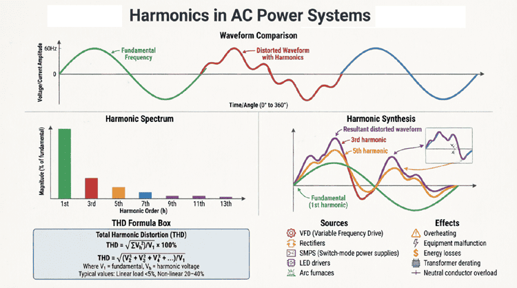
Harmonics are voltage or current waveforms at frequencies that are integer multiples of the fundamental power frequency (50/60 Hz). They are caused by non-linear loads that draw current in non-sinusoidal pulses. Harmonics distort the waveform, reduce power quality, and can cause equipment overheating, malfunctions, and increased energy losses.
Understanding Harmonic Fundamentals
What is a Harmonic?
A harmonic is a sinusoidal component of a periodic waveform that has a frequency equal to an integer multiple of the fundamental frequency.
Fundamental Frequency (1st Harmonic):
- The primary frequency of the power system
- 60 Hz in North America, 50 Hz in Europe and most other regions
- Represents the desired, useful component of the waveform
Harmonic Frequencies:
- 2nd harmonic: 2 × fundamental = 120 Hz (for 60 Hz system)
- 3rd harmonic: 3 × fundamental = 180 Hz
- 5th harmonic: 5 × fundamental = 300 Hz
- 7th harmonic: 7 × fundamental = 420 Hz
- nth harmonic: n × fundamental frequency
Harmonic Order and Classification
Harmonics are classified by their order (the integer multiple):
Odd Harmonics (3rd, 5th, 7th, 9th, 11th, 13th…):
- Most common in power systems
- Caused by typical non-linear loads
- Generally more problematic than even harmonics
Even Harmonics (2nd, 4th, 6th, 8th…):
- Less common in balanced systems
- Often indicate asymmetry or DC offset
- Usually smaller in magnitude
Triplen Harmonics (3rd, 9th, 15th, 21st…):
- Multiples of 3 (3n harmonics)
- Also called “zero-sequence” harmonics
- Add in the neutral conductor of three-phase systems
- Can cause severe neutral overheating
Dominant Harmonics:
In most power systems, the 5th and 7th harmonics are the most significant, followed by the 11th and 13th. The 3rd harmonic is also significant, especially in single-phase loads.
Fourier Series and Harmonic Analysis
Any periodic distorted waveform can be mathematically decomposed into its constituent sine waves using Fourier Series analysis:
$f(t) = A_0 + \sum_{n=1}^{\infty} [A_n \sin(n\omega t) + B_n \cos(n\omega t)]$
Where:
- $A_0$ = DC component (average value)
- $n$ = Harmonic order (1, 2, 3, …)
- $\omega$ = Angular frequency of fundamental (2πf)
- $A_n, B_n$ = Coefficients representing the magnitude of each harmonic
This mathematical foundation allows us to analyze complex waveforms and quantify harmonic content.
What causes harmonics in electrical systems?
Harmonics are caused by non-linear loads that draw current in non-sinusoidal pulses rather than smooth sine waves. Common sources include variable frequency drives, switching power supplies, computers, LED drivers, rectifiers, and electronic ballasts. These devices draw current only during specific portions of the voltage cycle, creating distorted current waveforms rich in harmonic frequencies.
Sources of Harmonics
Non-Linear Loads
The primary source of harmonics in modern power systems is non-linear loads. Unlike linear loads (resistors, induction motors) where current is proportional to voltage, non-linear loads draw current in a non-proportional manner.
Major Sources of Harmonics:
1. Variable Frequency Drives (VFDs):
- Used for motor speed control
- Contain rectifiers that convert AC to DC
- Draw current in short pulses near voltage peaks
- Generate significant 5th, 7th, 11th, and 13th harmonics
- One of the largest harmonic sources in industrial facilities
2. Switching Power Supplies:
- Found in computers, servers, telecommunications equipment
- Use rectifiers and DC-DC converters
- Draw current in brief, high-amplitude pulses
- Generate 3rd, 5th, and 7th harmonics
- Ubiquitous in commercial buildings
3. LED Lighting:
- LED drivers contain switching converters
- Draw non-sinusoidal current
- Can generate significant harmonics, especially 3rd
- Widespread adoption has increased harmonic levels
4. Uninterruptible Power Supplies (UPS):
- Rectifier/charger circuits generate harmonics
- Particularly when charging batteries
- Can inject harmonics back into the power system
5. Arc Furnaces and Welding Equipment:
- Create highly non-linear, time-varying loads
- Generate both harmonics and interharmonics
- Cause voltage fluctuations and flicker
6. Battery Chargers:
- Simple rectifier circuits
- Draw current in pulses
- Common in industrial and commercial settings
7. Electronic Ballasts:
- Used in fluorescent lighting
- High-frequency switching creates harmonics
- Less problematic than older magnetic ballasts
Harmonic Generation Mechanism
The mechanism of harmonic generation can be understood by examining a simple rectifier circuit:
Single-Phase Rectifier:
- Diodes conduct only when voltage exceeds capacitor voltage
- Current flows in short pulses near voltage peaks
- These pulses contain rich harmonic content
- Fourier analysis reveals multiples of fundamental frequency
Three-Phase Rectifier:
- Six-pulse rectifiers (most common in VFDs)
- Generate characteristic harmonics: 5th, 7th, 11th, 13th, 17th, 19th…
- Formula: $h = n \times p \pm 1$
- Where $h$ = harmonic order
- $n$ = positive integer (1, 2, 3…)
- $p$ = pulse number (6 for standard rectifier)
Measuring Harmonics: Total Harmonic Distortion (THD)
What is THD?
Total Harmonic Distortion (THD) is the most common metric for quantifying harmonic distortion. It represents the ratio of the root-mean-square (RMS) value of all harmonic components to the RMS value of the fundamental frequency, expressed as a percentage.
THD Formulas
For Voltage:
$THD_V = \frac{\sqrt{V_2^2 + V_3^2 + V_4^2 + … + V_n^2}}{V_1} \times 100\%$
For Current:
$THD_I = \frac{\sqrt{I_2^2 + I_3^2 + I_4^2 + … + I_n^2}}{I_1} \times 100\%$
Where:
- $V_1, I_1$ = RMS value of fundamental (1st harmonic)
- $V_2, I_2$ = RMS value of 2nd harmonic
- $V_3, I_3$ = RMS value of 3rd harmonic
- $V_n, I_n$ = RMS value of nth harmonic
Interpreting THD Values
Voltage THD (THD-V):
- < 5%: Excellent (typical for utility distribution)
- 5-8%: Acceptable (within IEEE 519 limits)
- 8-10%: Marginal (may cause issues with sensitive equipment)
- > 10%: Poor (likely to cause problems)
Current THD (THD-I):
- Varies widely depending on load type
- Linear loads: < 5%
- Modern electronic equipment: 20-100%
- VFDs without filters: 80-120%
- VFDs with filters: 5-10%
Individual Harmonic Distortion (IHD)
While THD provides an overall measure, Individual Harmonic Distortion (IHD) shows the contribution of each specific harmonic:
$IHD_n = \frac{H_n}{H_1} \times 100\%$
Where $H_n$ is the magnitude of the nth harmonic and $H_1$ is the fundamental.
This helps identify which specific harmonics are problematic.
IEEE 519 Standards
IEEE Standard 519-2014 establishes limits for harmonic distortion in power systems:
Voltage Distortion Limits:
- For systems < 69 kV: THD-V ≤ 5%
- Individual harmonic ≤ 3%
Current Distortion Limits:
- Depends on short-circuit ratio (Isc/IL)
- Typically 5-20% for individual harmonics
- Higher limits for systems with high fault current
These standards protect both utilities and customers from excessive harmonic distortion.
What is Total Harmonic Distortion (THD)?
THD is the ratio of the RMS value of all harmonic components to the RMS value of the fundamental frequency, expressed as a percentage. For voltage: THD = √(V₂² + V₃² + … + V²) / V₁ × 100%. IEEE 519 recommends keeping voltage THD below 5% for most power systems.
Effects of Harmonics on Power Systems
Thermal Effects
1. Transformer Overheating:
- Harmonic currents cause additional I²R losses
- Eddy current losses increase with frequency squared
- Can reduce transformer capacity by 20-40%
- May require derating or oversized transformers
- Special “K-factor” transformers designed for harmonic loads
2. Motor Overheating:
- Harmonic voltages cause additional copper and iron losses
- Reduce motor efficiency
- Increase operating temperature
- Shorten insulation life
- Can cause torque pulsations and vibration
3. Neutral Conductor Overheating:
- Triplen harmonics (3rd, 9th, 15th) add in neutral
- Neutral current can exceed phase current
- In severe cases: Neutral current = 1.73 × phase current
- Risk of fire if neutral is undersized
- Common problem in commercial buildings with many computers
Equipment Malfunction
1. Circuit Breaker Nuisance Tripping:
- Harmonic currents can cause false tripping
- Thermal-magnetic breakers misinterpret harmonic heating
- Electronic trip units may malfunction
- Leads to unplanned outages
2. Protective Relay Errors:
- Harmonics distort current and voltage waveforms
- Can cause incorrect relay operation
- May fail to trip during faults or trip unnecessarily
- Compromises system protection
3. Metering Errors:
- Meters calibrated for sine waves give incorrect readings
- Energy measurement errors
- Billing inaccuracies
- Power factor measurement errors
4. Communication Interference:
- Harmonics induce noise in communication cables
- Telephone interference (especially 3rd harmonic)
- Data corruption in digital systems
- Reduced signal quality
Power Quality Issues
1. Reduced Power Factor:
- Harmonics create distortion power factor
- Overall PF = Displacement PF × Distortion PF
- Even with unity displacement PF, harmonics reduce overall PF
- Increases apparent power demand
- May incur utility penalties
2. Resonance Conditions:
- Interaction between system inductance and capacitance
- Can amplify specific harmonics dramatically
- Parallel resonance: High impedance at resonant frequency
- Series resonance: Low impedance, high current
- Can cause equipment damage and capacitor failures
3. Voltage Distortion:
- Harmonic currents flowing through system impedance
- Create harmonic voltage drops
- Distort voltage waveform at point of common coupling (PCC)
- Affect other customers on the same system
4. Capacitor Bank Failures:
- Capacitors have lower impedance at higher frequencies
- Attract harmonic currents
- Overload and overheat
- Can fail catastrophically
- Common problem in power factor correction systems
Harmonic Mitigation Techniques
Passive Filters
Single-Tuned Filters:
- LC circuit tuned to specific harmonic frequency
- Provides low-impedance path for that harmonic
- Most common for 5th and 7th harmonics
- Relatively inexpensive
- Can be combined with power factor correction capacitors
High-Pass Filters:
- Pass all harmonics above a certain frequency
- Used when multiple high-order harmonics are present
- More complex than single-tuned filters
- Effective for harmonics above 11th or 13th
Detuned Filters:
- Capacitor banks with series reactors
- Tuned below dominant harmonic (typically 4.7th harmonic)
- Prevent resonance while providing power factor correction
- Protect capacitors from harmonic overload
Active Filters
Active Harmonic Filters (AHF):
- Use power electronics (IGBTs) to inject compensating currents
- Cancel harmonic currents in real-time
- Can mitigate multiple harmonics simultaneously
- Adaptive to changing load conditions
- More expensive than passive filters but more flexible
- Typical performance: Reduce THD from 100% to < 5%
Hybrid Filters:
- Combination of passive and active filters
- Passive filters handle dominant low-order harmonics
- Active filter handles remaining harmonics
- Cost-effective solution for complex harmonic problems
Multi-Pulse Converters
12-Pulse Converters:
- Use phase-shifting transformer
- Two 6-pulse rectifiers with 30° phase shift
- Cancel 5th and 7th harmonics
- Generate 11th, 13th, 23rd, 25th… (much lower magnitude)
- THD reduced from ~100% to ~10%
18-Pulse and 24-Pulse Converters:
- Further reduce harmonic content
- More complex and expensive
- Used in high-power applications
- THD can be reduced to < 5%
Line Reactors and DC Chokes
AC Line Reactors:
- Inductors installed on input of VFDs
- Increase source impedance
- Smooth current pulses
- Reduce THD from ~100% to 30-40%
- Inexpensive and simple
- Also provide short-circuit protection
DC Chokes:
- Installed in DC link of VFDs
- Smooth DC current
- Reduce harmonic generation
- More effective than AC reactors
- THD reduction to 30-35%
Isolation Transformers
K-Factor Transformers:
- Designed to handle harmonic loads
- Oversized conductors reduce heating
- Electrostatic shielding reduces harmonic transfer
- Rated for specific harmonic spectra
- Prevent harmonic propagation to upstream systems
Harmonic Mitigating Transformers (HMT):
- Use phase-shifting windings
- Cancel triplen harmonics in secondary
- Reduce voltage distortion
- Improve power quality for downstream loads
Best Practices for Harmonic Control
1. At the Design Stage:
- Specify low-harmonic equipment (VFDs with built-in filters)
- Use multi-pulse converters for large loads
- Size neutral conductors for harmonic currents (200% of phase)
- Install isolated neutral-ground bonds
- Plan for harmonic mitigation from the start
2. During Operation:
- Monitor harmonic levels regularly
- Use power quality analyzers
- Maintain capacitor banks properly
- Avoid resonance conditions
- Follow IEEE 519 guidelines
3. For Existing Problems:
- Conduct harmonic audit
- Identify major harmonic sources
- Install appropriate filters
- Consider active filters for variable loads
- Upgrade transformers if necessary
Practical Examples and Calculations
Example 1: Calculating THD
Problem: A voltage waveform has the following harmonic content:
- Fundamental (1st): 480V
- 3rd harmonic: 15V
- 5th harmonic: 24V
- 7th harmonic: 12V
- All other harmonics: negligible
Calculate the Total Harmonic Distortion (THD).
Solution:
Given:
- $V_1 = 480\text{V}$
- $V_3 = 15\text{V}$
- $V_5 = 24\text{V}$
- $V_7 = 12\text{V}$
Calculate THD:
$THD_V = \frac{\sqrt{V_3^2 + V_5^2 + V_7^2}}{V_1} \times 100\%$
$THD_V = \frac{\sqrt{15^2 + 24^2 + 12^2}}{480} \times 100\%$
$THD_V = \frac{\sqrt{225 + 576 + 144}}{480} \times 100\%$
$THD_V = \frac{\sqrt{945}}{480} \times 100\%$
$THD_V = \frac{30.74}{480} \times 100\%$
$THD_V = 6.4\%$
Interpretation: This exceeds the IEEE 519 recommended limit of 5%, indicating a power quality issue that should be addressed.
Example 2: Neutral Current with Triplen Harmonics
Problem: A three-phase, four-wire system supplies single-phase non-linear loads. Each phase carries:
- Fundamental current: 100A
- 3rd harmonic current: 60A
- 5th harmonic current: 30A
- 7th harmonic current: 15A
Calculate the neutral current.
Solution:
Key Principle:
- Fundamental currents (120° apart) cancel in neutral
- 3rd harmonics (in phase) add arithmetically in neutral
- Other harmonics partially cancel
Neutral Current Calculation:
For triplen harmonics (3rd, 9th, 15th…):
$I_N(3rd) = 3 \times I_3 = 3 \times 60 = 180\text{A}$
For other harmonics, they largely cancel, so we’ll approximate:
$I_N \approx I_N(3rd) = 180\text{A}$
Total RMS Neutral Current:
$I_{N(RMS)} = 180\text{A}$
Compare to Phase Current:
Phase current RMS = $\sqrt{100^2 + 60^2 + 30^2 + 15^2}$
Phase current RMS = $\sqrt{10000 + 3600 + 900 + 225}$
Phase current RMS = $\sqrt{14725} = 121\text{A}$
Result: Neutral current (180A) > Phase current (121A)!
This demonstrates why neutral conductors must be oversized in systems with significant triplen harmonics.
Example 3: Transformer Derating for Harmonics
Problem: A 1000 kVA transformer supplies a load with the following harmonic spectrum:
- Fundamental: 100%
- 3rd: 5%
- 5th: 20%
- 7th: 12%
- 9th: 3%
- 11th: 8%
- 13th: 5%
Calculate the K-factor and required derating.
Solution:
K-Factor Formula:
$K = \sum_{n=1}^{\infty} (I_n^2 \times n^2)$
Where $I_n$ is the per-unit current at harmonic n.
Calculation:
$K = (1.0^2 \times 1^2) + (0.05^2 \times 3^2) + (0.20^2 \times 5^2) + (0.12^2 \times 7^2) + (0.03^2 \times 9^2) + (0.08^2 \times 11^2) + (0.05^2 \times 13^2)$
$K = 1.0 + 0.0225 + 1.0 + 0.7056 + 0.0729 + 0.7744 + 0.4225$
$K = 4.0$
Derating:
For K-4, the transformer should be derated to approximately 85-90% of rated capacity.
Usable Capacity:
$1000 \text{ kVA} \times 0.875 = 875 \text{ kVA}$
The transformer should be loaded to no more than 875 kVA to avoid overheating.
Summary and Conclusion
Harmonics represent one of the most significant power quality challenges in modern electrical systems. The widespread adoption of non-linear loads has transformed harmonics from a niche concern into a critical issue affecting industrial, commercial, and even residential facilities.
Key takeaways from this guide include:
- Definition: Harmonics are integer multiples of the fundamental frequency (50/60 Hz) caused by non-linear loads drawing current in non-sinusoidal pulses
- Measurement: Total Harmonic Distortion (THD) quantifies harmonic content; IEEE 519 recommends voltage THD < 5%
- Major Sources: VFDs, switching power supplies, LED drivers, computers, and rectifiers are the primary harmonic generators
- Effects: Harmonics cause transformer and motor overheating, neutral conductor overload, equipment malfunction, resonance conditions, and reduced power factor
- Triplen Harmonics: 3rd, 9th, and 15th harmonics add in the neutral conductor, potentially causing neutral current to exceed phase current
- Mitigation Techniques:
- Passive filters (single-tuned, high-pass)
- Active harmonic filters (most flexible)
- Multi-pulse converters (12-pulse, 18-pulse)
- Line reactors and DC chokes
- K-factor and harmonic mitigating transformers
- Best Practices: Address harmonics at the design stage, specify low-harmonic equipment, monitor levels regularly, and follow IEEE 519 guidelines
Understanding and managing harmonics is essential for maintaining power quality, ensuring equipment reliability, and optimizing energy efficiency. Whether you’re designing a new facility, troubleshooting power quality issues, or upgrading existing systems, the principles and techniques outlined in this guide provide the foundation for effective harmonic management.
As electrical systems continue to evolve with increasing penetration of power electronics and renewable energy sources, harmonic analysis and mitigation will remain critical skills for electrical engineers and power quality professionals.