Series RLC Circuit Analysis
Introduction to the Series RLC Circuit
Throughout our exploration of AC circuit theory, we have studied the resistor (R), the inductor (L), and the capacitor (C) as individual, isolated components. We have seen how each uniquely affects the phase relationship between voltage and current, and how each opposes current flow through resistance, inductive reactance, and capacitive reactance.
However, in the real world of electrical engineering, these components rarely exist in isolation. They are combined to create complex networks that filter signals, tune radios, correct power factors, and drive motors. The most fundamental of these combined networks is the Series RLC Circuit, where a resistor, an inductor, and a capacitor are connected end-to-end in a single continuous loop across an AC voltage source.
Analyzing a series RLC circuit requires us to synthesize everything we have learned so far. We must combine scalar resistance with vector reactance, calculate complex impedance, determine the overall phase angle, and understand how voltages across individual components can sometimes exceed the total source voltage. This comprehensive guide will walk you through the step-by-step analysis of the series RLC circuit, equipping you with the skills to solve any AC network problem.
What is a Series RLC Circuit?
A series RLC circuit is an AC electrical circuit where a resistor (R), an inductor (L), and a capacitor (C) are connected in a single series loop. In this configuration, the exact same current flows through all three components, but the voltage drops across each component will differ in both magnitude and phase angle.
The Golden Rule of Series Circuits: Current is the Reference
Before we begin calculating voltages and impedance, we must establish the foundational rule of series circuit analysis: In a series circuit, the current is the same everywhere.
Because the same alternating current flows through the resistor, the inductor, and the capacitor sequentially, it is highly convenient to use the current phasor ($I$) as our reference vector. We draw the current phasor horizontally along the 0° axis. All voltage drops are then drawn and calculated relative to this reference current.
Voltage Drops Across Each Component
Based on the individual characteristics of R, L, and C, we know exactly how their respective voltage drops relate to the reference current:
- Resistor Voltage ($V_R$): In a resistor, voltage and current are in phase. Therefore, the $V_R$ phasor points in the exact same direction as the current reference (0°).
- Inductor Voltage ($V_L$): In an inductor, voltage leads current by 90°. Therefore, the $V_L$ phasor points straight up along the positive imaginary (+j) axis.
- Capacitor Voltage ($V_C$): In a capacitor, voltage lags current by 90°. Therefore, the $V_C$ phasor points straight down along the negative imaginary (-j) axis.
Because $V_L$ and $V_C$ point in directly opposite directions on the complex plane, they inherently oppose each other. The net reactive voltage is simply the difference between the two: $V_X = V_L – V_C$.
Calculating Total Impedance in a Series RLC Circuit
Impedance ($Z$) is the total opposition to current flow in an AC circuit. In a series RLC circuit, the total impedance is the phasor sum of the resistance ($R$) and the net reactance ($X$).
The Net Reactance ($X$)
Since inductive reactance ($X_L$) and capacitive reactance ($X_C$) are 180 degrees out of phase with each other, they subtract rather than add. The net reactance is:
$X = X_L – X_C$
- If $X_L > X_C$, the net reactance is positive, and the circuit behaves inductively (current lags voltage).
- If $X_C > X_L$, the net reactance is negative, and the circuit behaves capacitively (current leads voltage).
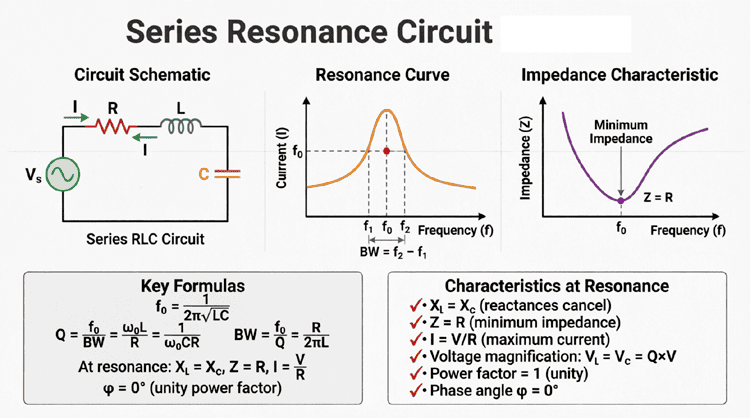
- If $X_L = X_C$, the net reactance is zero, and the circuit is purely resistive (this special condition is known as resonance, covered in a future article).
The Impedance Formula
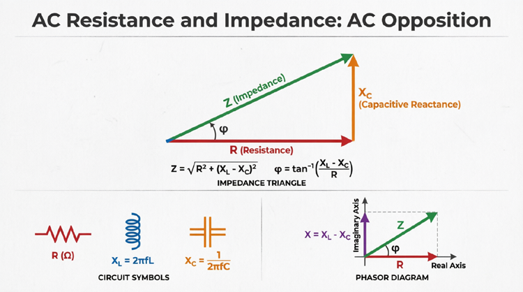
Because resistance and net reactance are 90 degrees out of phase, we cannot simply add them arithmetically ($Z \neq R + X$). Instead, we use the Pythagorean theorem to find the magnitude of the total impedance:
$Z = \sqrt{R^2 + (X_L – X_C)^2}$
The Impedance Triangle
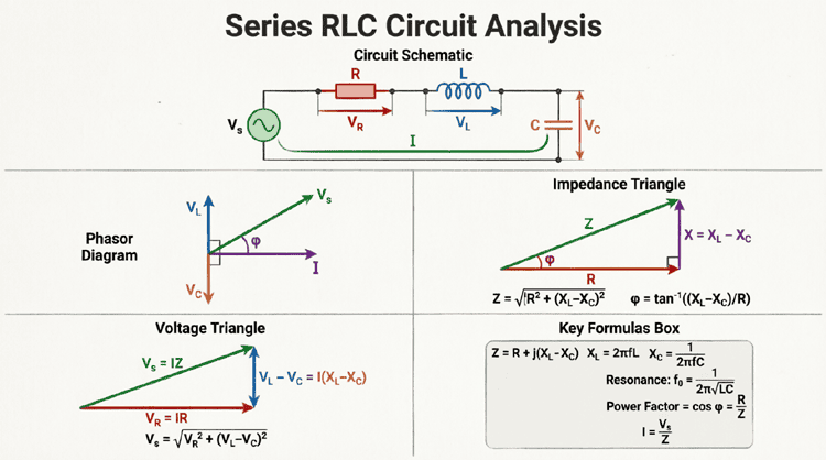
The relationship between $R$, $X$, and $Z$ is beautifully visualized using the Impedance Triangle.
Diagram Description: The Soft Sky Blue horizontal line represents pure Resistance (R). The Soft Orange vertical line represents the Net Reactance (X). The Soft Green diagonal line represents the Total Impedance (Z). The angle θ between R and Z is the circuit’s phase angle.
Phase Angle and Power Factor
The phase angle ($\theta$) of a series RLC circuit tells us the exact degree by which the total current lags or leads the source voltage. It is calculated using the trigonometric tangent function based on the impedance triangle:
$\theta = \arctan\left(\frac{X_L – X_C}{R}\right)$
The phase angle is directly tied to the Power Factor (PF) of the circuit, which is the cosine of the phase angle:
Power Factor = $\cos(\theta) = \frac{R}{Z}$
- A positive $\theta$ indicates a lagging power factor (inductive dominance).
- A negative $\theta$ indicates a leading power factor (capacitive dominance).
How do you calculate impedance in a series RLC circuit?
To calculate total impedance (Z) in a series RLC circuit, first find the net reactance by subtracting capacitive reactance from inductive reactance (X = X_L – X_C). Then, use the Pythagorean theorem: Z = √(R² + X²). The result is the total opposition to AC current flow, measured in ohms.
Step-by-Step Example
Let’s put theory into practice with a complete, step-by-step analysis of a series RLC circuit.
Problem Statement:
A series RLC circuit is connected to a 120V (RMS), 60Hz AC source. The circuit contains:
- A Resistor: $R = 30 \Omega$
- An Inductor with an inductive reactance: $X_L = 40 \Omega$
- A Capacitor with a capacitive reactance: $X_C = 10 \Omega$
Calculate the total impedance, total current, individual voltage drops, and the phase angle.
Step 1: Calculate Net Reactance and Total Impedance
First, find the net reactance ($X$):
$X = X_L – X_C = 40 \Omega – 10 \Omega = 30 \Omega$ (Since it’s positive, the circuit is net inductive).
Next, calculate the total impedance ($Z$):
$Z = \sqrt{R^2 + X^2}$
$Z = \sqrt{30^2 + 30^2}$
$Z = \sqrt{900 + 900} = \sqrt{1800}$
$Z \approx 42.43 \Omega$
Step 2: Calculate Total Current
Using Ohm’s Law for AC circuits ($I = V / Z$):
$I = \frac{120\text{V}}{42.43\Omega}$
$I \approx 2.83 \text{ Amps (RMS)}$
Note: Because this is a series circuit, this exact same current of 2.83A flows through the resistor, the inductor, and the capacitor.
Step 3: Calculate Individual Voltage Drops
Now we calculate the voltage drop across each individual component using Ohm’s Law ($V = I \times \text{Opposition}$):
- Voltage across Resistor ($V_R$):
$V_R = I \times R = 2.83 \text{A} \times 30 \Omega = \mathbf{84.9 \text{ V}}$ - Voltage across Inductor ($V_L$):
$V_L = I \times X_L = 2.83 \text{A} \times 40 \Omega = \mathbf{113.2 \text{ V}}$ - Voltage across Capacitor ($V_C$):
$V_C = I \times X_C = 2.83 \text{A} \times 10 \Omega = \mathbf{28.3 \text{ V}}$
Step 4: Verify the Source Voltage (Kirchhoff’s Voltage Law)
Here is where many students make a critical mistake. If you simply add the voltage drops arithmetically ($84.9 + 113.2 + 28.3$), you get 226.4V, which is much higher than our 120V source!
Why? Because AC voltages are phasors, not scalars. They have phase angles. To find the true source voltage ($V_S$), we must add them vectorially:
$V_S = \sqrt{V_R^2 + (V_L – V_C)^2}$
$V_S = \sqrt{84.9^2 + (113.2 – 28.3)^2}$
$V_S = \sqrt{7208 + (84.9)^2}$
$V_S = \sqrt{7208 + 7208} = \sqrt{14416}$
$V_S \approx 120 \text{ V}$
The math perfectly matches our source voltage, verifying our calculations!
Step 5: Calculate the Phase Angle
Finally, we calculate the phase angle ($\theta$) of the circuit:
$\theta = \arctan\left(\frac{X_L – X_C}{R}\right) = \arctan\left(\frac{30}{30}\right) = \arctan(1)$
$\theta = 45^\circ$
Because the net reactance is inductive, the total current lags the source voltage by 45 degrees.
Can the voltage across an inductor or capacitor be greater than the source voltage in a series RLC circuit?
Yes, absolutely. Because the voltages across the inductor and capacitor are 180 degrees out of phase, they oppose and cancel each other out in the overall phasor sum. Consequently, the individual voltage drops across L or C can be significantly higher than the total applied source voltage, even though their combined vector sum plus the resistive drop equals the source voltage.
Visualizing the Voltage Phasor Diagram
To truly understand the relationships in our practical example, we can draw a Voltage Phasor Diagram. Remember, we use the current ($I$) as our horizontal reference (0°).
Diagram Description: The Soft Sky Blue vector represents $V_R$ on the horizontal axis. The Soft Plum vector represents $V_L$ pointing straight up. The Soft Teal vector represents $V_C$ pointing straight down. Because $V_L$ is larger than $V_C$, the net reactive voltage points up. The Dark Slate vector represents the total Source Voltage ($V_S$), connecting the origin to the final tip, leading the current by 45 degrees.
Power in a Series RLC Circuit
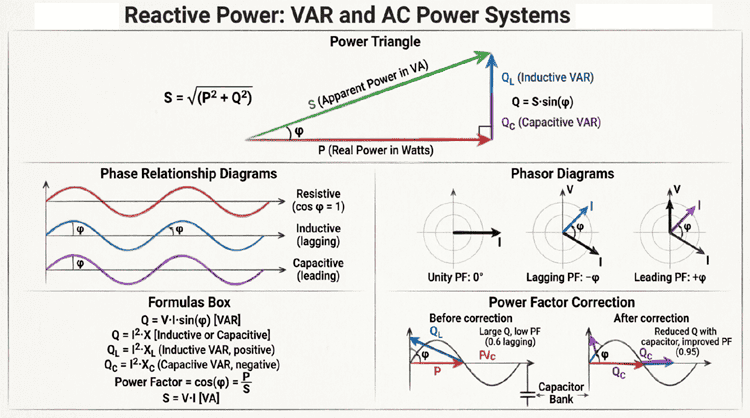
Just like in individual component circuits, a series RLC circuit consumes Real Power, exchanges Reactive Power, and draws Apparent Power.
Real Power (P)
Real power is the power actually consumed and dissipated as heat. Only the resistor consumes real power; ideal inductors and capacitors consume zero real power.
$P = I^2 \times R$ (or $P = V_R \times I$)
Measured in Watts (W).
Reactive Power (Q)
Reactive power is the power continuously exchanged between the source and the reactive components (L and C). Because $X_L$ and $X_C$ oppose each other, we use the net reactance to calculate total reactive power.
$Q = I^2 \times X$ (where $X = X_L – X_C$)
Measured in Volt-Amperes Reactive (VAR).
Apparent Power (S)
Apparent power is the total power supplied by the source, calculated using the total impedance.
$S = I^2 \times Z$ (or $S = V_S \times I$)
Measured in Volt-Amperes (VA).
The Power Triangle
These three power values form the Power Triangle, which is geometrically identical in shape to the Impedance Triangle, just scaled by the factor of $I^2$.
$S = \sqrt{P^2 + Q^2}$
Let’s calculate the power for our practical example ($I = 2.83A$):
- Real Power (P): $2.83^2 \times 30 = 8.01 \times 30 = \mathbf{240.3 \text{ W}}$
- Reactive Power (Q): $2.83^2 \times 30 = 8.01 \times 30 = \mathbf{240.3 \text{ VAR}}$
- Apparent Power (S): $2.83^2 \times 42.43 = 8.01 \times 42.43 = \mathbf{339.8 \text{ VA}}$
Notice that because $R = X$ in this specific example ($30 \Omega$ each), the Real Power and Reactive Power are exactly equal, resulting in a 45-degree phase angle and a power factor of $\cos(45^\circ) = 0.707$.
Practical Applications of Series RLC Circuits
Understanding series RLC analysis is not just an academic exercise; it is the foundation for numerous real-world electrical and electronic systems.
1. Analog Filters
Series RLC circuits are the building blocks of analog frequency filters. Because the reactance of L and C changes with frequency, the total impedance of the circuit changes with frequency. By taking the output voltage across specific components (e.g., across the capacitor for a low-pass filter, or across the inductor for a high-pass filter), engineers can design circuits that block unwanted frequencies and pass desired ones.
2. Radio Tuning (Tank Circuits)
In AM/FM radios, a variable capacitor and an inductor form a series (or parallel) RLC circuit. By adjusting the capacitance, you change the resonant frequency of the circuit. When the circuit’s resonant frequency matches the frequency of a specific radio station’s broadcast signal, the impedance drops to a minimum (limited only by the resistance), allowing maximum current to flow for that specific station while rejecting all others.
3. Power Factor Correction
While parallel configurations are more common for large-scale power factor correction, understanding the series interaction of L and C is vital. If a circuit is too inductive (current lagging), adding capacitance in the circuit reduces the net reactance, bringing the phase angle closer to zero, improving the power factor, and reducing line losses.
4. Induction Heating and Surge Protection
Series RLC circuits are used in induction heating, where a high-frequency AC source drives a series resonant circuit to create massive currents in a workpiece (like metal). They are also used in surge protection circuits, where the inductor blocks high-frequency voltage spikes while the capacitor shunts them safely to ground.
Summary and Conclusion
The series RLC circuit is the ultimate proving ground for AC circuit theory. It forces us to move beyond simple scalar arithmetic and embrace the vector nature of alternating current. By combining the energy-dissipating resistor, the magnetic energy-storing inductor, and the electric energy-storing capacitor, we create a dynamic system where voltages can cancel each other out, phase shifts dictate power efficiency, and impedance governs the flow of energy.
Key takeaways from this guide include:
- Reference Phasor: In a series circuit, current is constant and serves as the 0° reference phasor.
- Impedance Calculation: Total impedance is the vector sum of resistance and net reactance: $Z = \sqrt{R^2 + (X_L – X_C)^2}$.
- Voltage Cancellation: The voltages across the inductor and capacitor are 180° out of phase and subtract from one another. Consequently, individual component voltages can exceed the source voltage.
- Phase Angle: The phase angle $\theta = \arctan((X_L – X_C) / R)$ determines whether the circuit is inductive (lagging) or capacitive (leading).
- Power Dynamics: Only the resistor consumes real power (Watts). The net reactance determines the reactive power (VAR), and together they form the apparent power (VA) drawn from the source.
Mastering the analysis of the series RLC circuit provides you with the analytical framework required to tackle any linear AC network. Whether you are designing a simple audio crossover, troubleshooting a motor control panel, or tuning a radio receiver, the principles of series RLC analysis are the indispensable tools of the electrical engineer.