Reactive Power
Reactive Power: VAR and AC Power Systems
Introduction to Reactive Power
In the world of alternating current (AC) electrical systems, reactive power is one of the most misunderstood yet crucial concepts. Unlike the real power that performs useful work—turning motors, lighting bulbs, and heating elements—reactive power doesn’t directly accomplish tangible tasks. Yet, without it, our modern electrical grid would collapse, motors wouldn’t spin, and transformers wouldn’t function.
Reactive power, measured in VAR (Volt-Amperes Reactive), represents the energy that oscillates back and forth between the source and reactive components (inductors and capacitors) in an AC circuit. This energy is temporarily stored in magnetic or electric fields during one part of the AC cycle and returned to the source during another part, resulting in zero net energy consumption over a complete cycle.
While reactive power doesn’t perform useful work, it is absolutely essential for:
- Establishing magnetic fields in motors and transformers
- Maintaining voltage levels in power transmission systems
- Enabling the operation of inductive and capacitive loads
- Supporting the stability of electrical grids
Understanding reactive power is critical for electrical engineers, power system operators, and anyone involved in designing or managing AC electrical systems. This comprehensive guide will explore the theory, mathematics, and practical implications of reactive power, complete with visual diagrams and real-world examples.
What is Reactive Power?
Reactive power (Q) is the portion of AC power that oscillates between the source and reactive components (inductors and capacitors) without being consumed. It is measured in VAR (Volt-Amperes Reactive) and is essential for creating magnetic and electric fields in AC equipment. While it performs no useful work, reactive power is necessary for the operation of motors, transformers, and power system stability.
Understanding the Nature of Reactive Power
Real Power vs. Reactive Power vs. Apparent Power
To understand reactive power, we must first distinguish it from the other two types of power in AC systems:
1. Real Power (P) – Measured in Watts (W)
- Also called “active power” or “true power”
- Represents energy that is actually consumed and converted to useful work
- Dissipated as heat, light, mechanical energy, etc.
- Always positive (flows from source to load)
- Calculated as: $P = V_{RMS} \times I_{RMS} \times \cos(\theta)$
2. Reactive Power (Q) – Measured in VAR (Volt-Amperes Reactive)
- Represents energy that oscillates between source and load
- Stored temporarily in magnetic or electric fields
- Returned to source each cycle (net consumption = 0)
- Can be positive (inductive) or negative (capacitive)
- Calculated as: $Q = V_{RMS} \times I_{RMS} \times \sin(\theta)$
3. Apparent Power (S) – Measured in VA (Volt-Amperes)
- Represents the total power supplied by the source
- Combination of real and reactive power
- Determines the size of conductors, transformers, and generators needed
- Calculated as: $S = V_{RMS} \times I_{RMS}$
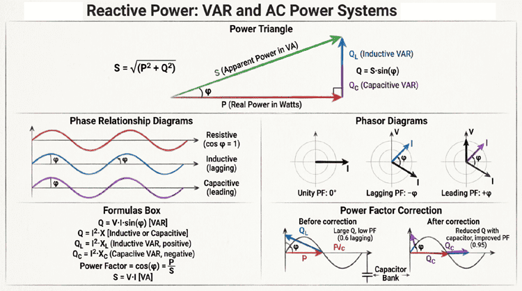
The Power Triangle
These three types of power form a right triangle known as the Power Triangle:
From the power triangle, we can derive:
$S = \sqrt{P^2 + Q^2}$
$\cos(\theta) = P/S$ (Power Factor)
$\sin(\theta) = Q/S$
$\tan(\theta) = Q/P$
Where θ is the phase angle between voltage and current.
What is the difference between real, reactive, and apparent power?
Real power (Watts) performs useful work and is consumed by the load. Reactive power (VAR) oscillates between source and load, creating magnetic/electric fields but doing no net work. Apparent power (VA) is the total power supplied, combining both real and reactive power: S = √(P² + Q²).
The Physics of Reactive Power
Energy Storage in Inductors
Inductors store energy in magnetic fields. When AC current flows through an inductor:
During the positive quarter-cycle:
- Current increases from zero to maximum
- Magnetic field builds up around the coil
- Energy is stored in the magnetic field
- Power flows FROM source TO inductor (positive power)
During the negative quarter-cycle:
- Current decreases from maximum to zero
- Magnetic field collapses
- Energy is returned FROM inductor TO source (negative power)
Net result over a complete cycle:
- Energy stored = Energy returned
- Net energy consumption = 0
- But reactive power flow is essential for the magnetic field
The reactive power for an inductor is:
$Q_L = I_{RMS}^2 \times X_L = \frac{V_{RMS}^2}{X_L}$
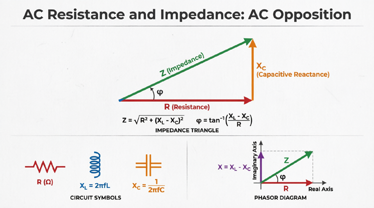
Where $X_L = 2\pi fL$ is the inductive reactance.
By convention, inductive reactive power is positive (Q > 0).
Energy Storage in Capacitors
Capacitors store energy in electric fields. When AC voltage is applied to a capacitor:
During the positive quarter-cycle:
- Voltage increases from zero to maximum
- Electric field builds between plates
- Charge accumulates on plates
- Energy is stored in the electric field
- Power flows FROM source TO capacitor
During the negative quarter-cycle:
- Voltage decreases from maximum to zero
- Electric field collapses
- Charge flows back to source
- Energy is returned FROM capacitor TO source
Net result over a complete cycle:
- Energy stored = Energy returned
- Net energy consumption = 0
The reactive power for a capacitor is:
$Q_C = I_{RMS}^2 \times X_C = \frac{V_{RMS}^2}{X_C}$
Where $X_C = 1/(2\pi fC)$ is the capacitive reactance.
By convention, capacitive reactive power is negative (Q < 0).
Why Reactive Power is Necessary
You might wonder: if reactive power doesn’t do useful work, why do we need it?
1. Motor Operation:
Induction motors and transformers require magnetic fields to operate. These magnetic fields are created by reactive power. Without reactive power, motors wouldn’t produce torque, and transformers wouldn’t transfer energy.
2. Voltage Support:
Reactive power helps maintain voltage levels in transmission systems. Insufficient reactive power causes voltage drops, while excess reactive power causes voltage rises. Grid operators carefully manage reactive power to keep voltages within acceptable limits.
3. System Stability:
Reactive power affects the stability of the electrical grid. During faults or disturbances, adequate reactive power reserves are essential to prevent voltage collapse and blackouts.
Mathematical Analysis of Reactive Power
Calculating Reactive Power
For a single-phase AC circuit with sinusoidal voltage and current:
General Formula:
$Q = V_{RMS} \times I_{RMS} \times \sin(\theta)$
Where:
- Q = Reactive power in VAR
- V_RMS = RMS voltage in volts
- I_RMS = RMS current in amperes
- θ = Phase angle between voltage and current
Reactive Power in Pure Components
Pure Inductor:
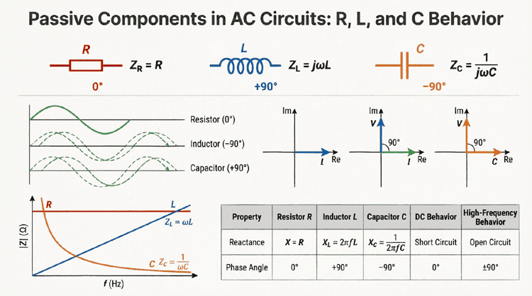
- Phase angle θ = 90° (current lags voltage)
- $\sin(90°) = 1$
- $Q_L = V_{RMS} \times I_{RMS}$ (positive)
Pure Capacitor:
- Phase angle θ = -90° (current leads voltage)
- $\sin(-90°) = -1$
- $Q_C = -V_{RMS} \times I_{RMS}$ (negative)
Pure Resistor:
- Phase angle θ = 0° (voltage and current in phase)
- $\sin(0°) = 0$
- $Q_R = 0$ (no reactive power)
Reactive Power Using Impedance
For a circuit with known impedance:
$Q = I_{RMS}^2 \times X$
Where X is the net reactance:
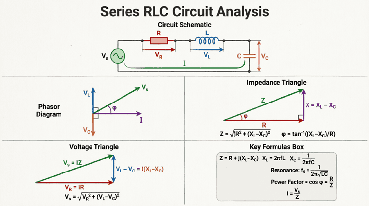
- $X = X_L – X_C$ (for series circuits)
- Positive X = inductive (Q > 0)
- Negative X = capacitive (Q < 0)
Alternatively:
$Q = \frac{V_{RMS}^2}{X}$
Three-Phase Reactive Power
For balanced three-phase systems:
$Q_{3\phi} = \sqrt{3} \times V_L \times I_L \times \sin(\theta)$
Or:
$Q_{3\phi} = 3 \times V_{phase} \times I_{phase} \times \sin(\theta)$
Where:
- $V_L$ = Line-to-line voltage
- $I_L$ = Line current
How do you calculate reactive power?
Reactive power is calculated using Q = V_RMS × I_RMS × sin(θ), where θ is the phase angle between voltage and current. For pure inductors, Q = V × I (positive). For pure capacitors, Q = -V × I (negative). In terms of reactance: Q = I²X or Q = V²/X.
Practical Examples and Calculations
Example 1: Calculating Reactive Power in an Inductive Load
Problem: A single-phase induction motor draws 10A from a 240V, 60Hz supply. The current lags the voltage by 36.87°. Calculate the reactive power.
Solution:
Given:
- $V_{RMS} = 240\text{V}$
- $I_{RMS} = 10\text{A}$
- $\theta = 36.87°$ (lagging, inductive)
Calculate Reactive Power:
$Q = V_{RMS} \times I_{RMS} \times \sin(\theta)$
$Q = 240 \times 10 \times \sin(36.87°)$
$Q = 2400 \times 0.6$
$Q = 1440 \text{ VAR} = 1.44 \text{ kVAR}$
Since the load is inductive (current lags), Q is positive.
Also calculate Real Power:
$P = V_{RMS} \times I_{RMS} \times \cos(\theta)$
$P = 240 \times 10 \times \cos(36.87°)$
$P = 2400 \times 0.8$
$P = 1920 \text{ W} = 1.92 \text{ kW}$
And Apparent Power:
$S = V_{RMS} \times I_{RMS}$
$S = 240 \times 10$
$S = 2400 \text{ VA} = 2.4 \text{ kVA}$
Verify Power Triangle:
$S = \sqrt{P^2 + Q^2}$
$S = \sqrt{1920^2 + 1440^2}$
$S = \sqrt{3,686,400 + 2,073,600}$
$S = \sqrt{5,760,000}$
$S = 2400 \text{ VA}$ ✓
Example 2: Capacitor Bank Reactive Power
Problem: A 50 μF capacitor is connected to a 480V, 60Hz supply. Calculate the reactive power supplied by the capacitor.
Solution:
Given:
- $C = 50 \text{ μF} = 50 \times 10^{-6} \text{ F}$
- $V_{RMS} = 480\text{V}$
- $f = 60 \text{ Hz}$
Step 1: Calculate Capacitive Reactance
$X_C = \frac{1}{2\pi fC}$
$X_C = \frac{1}{2\pi \times 60 \times 50 \times 10^{-6}}$
$X_C = \frac{1}{0.01885}$
$X_C = 53.05 \Omega$
Step 2: Calculate Reactive Power
$Q_C = \frac{V_{RMS}^2}{X_C}$
$Q_C = \frac{480^2}{53.05}$
$Q_C = \frac{230,400}{53.05}$
$Q_C = -4,344 \text{ VAR} = -4.34 \text{ kVAR}$
The negative sign indicates capacitive reactive power (supplying VARs to the system).
Example 3: Power Factor Correction
Problem: An industrial facility has a load of 500 kW with a power factor of 0.75 lagging. Calculate the reactive power required to improve the power factor to 0.95 lagging.
Solution:
Given:
- $P = 500 \text{ kW}$
- $PF_1 = 0.75$ (initial)
- $PF_2 = 0.95$ (target)
Step 1: Calculate Initial Reactive Power
$\theta_1 = \arccos(0.75) = 41.41°$
$Q_1 = P \times \tan(\theta_1)$
$Q_1 = 500 \times \tan(41.41°)$
$Q_1 = 500 \times 0.882$
$Q_1 = 441 \text{ kVAR}$ (inductive)
Step 2: Calculate Target Reactive Power
$\theta_2 = \arccos(0.95) = 18.19°$
$Q_2 = P \times \tan(\theta_2)$
$Q_2 = 500 \times \tan(18.19°)$
$Q_2 = 500 \times 0.329$
$Q_2 = 164.5 \text{ kVAR}$ (inductive)
Step 3: Calculate Required Capacitor Bank
$Q_{capacitor} = Q_1 – Q_2$
$Q_{capacitor} = 441 – 164.5$
$Q_{capacitor} = 276.5 \text{ kVAR}$ (capacitive)
A 276.5 kVAR capacitor bank is needed to improve the power factor from 0.75 to 0.95.
Visualizing Reactive Power Flow
Instantaneous Power Waveform
The instantaneous power in an AC circuit with both real and reactive components shows interesting behavior:
The waveform shows:
- Positive portions: Energy flows from source to load
- Negative portions: Energy flows from load back to source
- Average value: Real power (P)
- Oscillating component: Reactive power (Q)
Power Triangle Visualization
The relationship between P, Q, and S is best visualized as a right triangle:
Reactive Power in Power Systems
Sources of Reactive Power
Inductive Loads (Consume VARs):
- Induction motors (largest consumers)
- Transformers
- Fluorescent lighting ballasts
- Induction furnaces
- Welding equipment
Capacitive Sources (Supply VARs):
- Capacitor banks
- Synchronous condensers
- Underground cables (capacitive effect)
- Long transmission lines (light load conditions)
Generators (Can Supply or Consume):
- Synchronous generators can supply or absorb reactive power depending on excitation
- Over-excited: Supplies VARs (capacitive behavior)
- Under-excited: Absorbs VARs (inductive behavior)
Reactive Power and Voltage Control
Reactive power has a direct relationship with voltage levels in power systems:
Insufficient Reactive Power:
- Causes voltage drops
- Can lead to voltage collapse
- Motors draw more current, worsening the problem
- May cause blackouts
Excess Reactive Power:
- Causes voltage rises
- Can damage equipment due to overvoltage
- Wastes transmission capacity
Optimal Reactive Power:
- Maintains voltage within ±5% of nominal
- Ensures system stability
- Maximizes transmission efficiency
Grid operators use various devices to manage reactive power:
- Capacitor banks (add VARs)
- Reactors (absorb VARs)
- Tap-changing transformers
- Static VAR compensators (SVCs)
- Synchronous condensers
Transmission of Reactive Power
Unlike real power, reactive power:
- Doesn’t travel well over long distances
- Causes significant I²R losses in transmission lines
- Should be supplied close to where it’s needed
This is why:
- Capacitor banks are installed at distribution substations
- Industrial facilities install local power factor correction
- Transmission systems have reactive power compensation at multiple points
Impact of Reactive Power on System Efficiency
Power Factor and Efficiency
Low Power Factor Problems:
When reactive power is high relative to real power (low power factor):
- Increased Current:
- For the same real power, lower PF requires higher current
- $I = P / (V \times PF)$
- Example: 100 kW at 480V
- PF = 1.0 → I = 208A
- PF = 0.7 → I = 297A (43% increase!)
- Higher Losses:
- Power losses = I²R
- Higher current means significantly higher losses
- 43% more current = 105% more losses!
- Larger Equipment:
- Conductors must be sized for higher current
- Transformers and generators must have higher kVA ratings
- Increased capital costs
- Utility Penalties:
- Many utilities charge penalties for PF < 0.9 or 0.95
- Increases electricity costs
Benefits of Power Factor Correction
By reducing reactive power demand through power factor correction:
- Reduced Current:
- Lower current for same real power
- Reduced I²R losses
- Lower energy costs
- Increased Capacity:
- Existing equipment can handle more real power
- Defers need for infrastructure upgrades
- Improved Voltage:
- Better voltage regulation
- Improved motor performance
- Longer equipment life
- Cost Savings:
- Lower electricity bills
- Avoided utility penalties
- Reduced maintenance costs
Measuring and Monitoring Reactive Power
Instruments for Reactive Power Measurement
1. VAR Meters:
- Directly measure reactive power
- Display in VAR or kVAR
- Used in industrial facilities and substations
2. Power Quality Analyzers:
- Measure P, Q, S, PF, harmonics
- Provide comprehensive power analysis
- Essential for troubleshooting
3. Smart Meters:
- Modern utility meters measure reactive energy (kVARh)
- Enable time-of-use billing for reactive power
- Provide data for grid management
4. Protective Relays:
- Monitor reactive power for system protection
- Detect abnormal conditions
- Trigger corrective actions
Reactive Energy Billing
While most residential customers are billed only for real energy (kWh), industrial customers are often charged for reactive energy (kVARh) or penalized for low power factor.
Billing Methods:
- kVARh Billing:
- Direct charge for reactive energy consumed
- Rate typically 10-50% of kWh rate
- Power Factor Penalty:
- Penalty if average PF < threshold (e.g., 0.95)
- Penalty = (Threshold PF – Actual PF) × Demand Charge
- kVA Demand Billing:
- Billed based on apparent power (kVA) rather than real power (kW)
- Automatically penalizes low power factor
Summary and Conclusion
Reactive power is a fundamental concept in AC electrical systems that, while not performing useful work directly, is absolutely essential for the operation of motors, transformers, and the stability of power grids. Understanding reactive power enables engineers to design efficient systems, optimize power factor, and ensure reliable electrical service.
Key takeaways from this guide include:
- Definition: Reactive power (Q) represents energy that oscillates between source and load, measured in VAR
- Power Triangle: $S = \sqrt{P^2 + Q^2}$, where S is apparent power and P is real power
- Calculation: $Q = V_{RMS} \times I_{RMS} \times \sin(\theta)$
- Inductive vs. Capacitive: Inductive loads consume VARs (Q > 0); capacitive loads supply VARs (Q < 0)
- Power Factor: $PF = \cos(\theta) = P/S$; low PF increases current and losses
- Voltage Support: Reactive power is critical for maintaining voltage levels in transmission systems
- Power Factor Correction: Capacitor banks reduce reactive power demand, improving efficiency and reducing costs
Mastering reactive power concepts equips you to design efficient electrical systems, reduce energy costs, and contribute to grid stability. Whether you’re sizing capacitor banks for an industrial facility, analyzing power quality issues, or managing a utility grid, understanding reactive power is essential for success in electrical engineering.