Basic Synchronizer Circuits
The basic synchronizer circuit should meet the following four basic requirements: It must be free running (astable). Because the synchronizer is the heart of the radar, it must establish the zero time reference and the prf (prr). )It should be stable in frequency.
For accurate ranging, the prr and its reciprocal, pulse-repetition time (prt), must not change between pulses. )The frequency must be variable to enable the radar to operate at different ranges. Three basic synchronizer circuits can meet the above-mentioned requirements. They are the SINE-WAVE OSCILLAOTR, the SINGLE-SWING BLOCKING OSCILLATOR, and the MASTER-TRIGGER (ASTABLE) MULTIVIBRATOR.
The block diagrams and waveforms of these three synchronizers as they are used in externally synchronized radar systems. In each case, equally spaced timing trigger pulses are produced. The prr of each series of timing trigger pulses is determined by the operating frequency of the associated master oscillators.
Sine-Wave Oscillator Synchronizer
In the sine-wave oscillator synchronizer, a sine-wave oscillator is used for the basic timing device (master oscillator). The oscillator output is applied to both an overdriven amplifier and the radar indicator. The sine waves applied to the overdriven amplifier are shaped into square waves. These squares waves are then converted into positive and negative timing trigger pulses by means of a short time constant RC differentiator. By means of a limiter, either the positive or negative trigger pulses from the RC differentiator are removed. This leaves trigger pulses of only one polarity. For example, the limiter in view A is a negative-lobe limiter; that is, the limiter removes the negative trigger pulses and passes only positive trigger pulses to the radar transmitter. A disadvantage of sine-wave oscillator synchronizer is the large number of pulse-shaping circuits required to produce the necessary timing trigger pulses.
Master Trigger (Astable) Multi-vibrator Synchronizer
In a master trigger (astable) multi-vibrator synchronizer, the master oscillator generally is an astable multi-vibrator. The multi-vibrator is either ASYMMETRICAL or SYMMETRICAL. If the multi-vibrator is asymmetrical, it generates rectangular waves. If the multi-vibrator is symmetrical, it generates square waves. In either case, the timing trigger pulses are equally spaced after a limiter removes undesired positive or negative lobes. There are two transistors in an astable multi-vibrator. The two output voltages are equal in amplitude, but are 180 degrees out of phase. The output of the astable multi-vibrator consists of positive and negative rectangular waves. Positive rectangular waves are applied to an RC differentiator and converted into positive and negative trigger pulses. As in the sine-wave synchronizer, the negative trigger pulses are removed by means of a negative-lobe limiter, and the positive pulses are applied to the transmitter. Both positive and negative rectangular waves from the astable multi-vibrator are applied to the indicator. One set of waves is used to intensify the cathode-ray tube electron beam for the duration of the sweep. The other set of waves is used to gate (turn on) the range marker generator.
Single-Swing Blocking Oscillator Synchronizer
In the single-swing, blocking-oscillator synchronizer, a free-running, single-swing blocking oscillator is generally used as the master oscillator. The advantage of the single-swing blocking oscillator is that it generates sharp trigger pulses without additional shaping circuitry. Timing trigger pulses of only one polarity are obtained by means of a limiter. Gating pulses for the indicator circuits are produced by applying the output of the blocking oscillator to a one-shot multi-vibrator. Crystal-controlled oscillators may be used when very stable frequency operation is required.
Modulator
A modulator is a device which turns the transmitting tube ON and OFF in such a manner as to generate the desired wavefor n. an illustration of a simple line pulses. It corresponds broadly to the high-level AM modulator. Here t anode of the output tube is modulated directly by a system that generates and provide large pulses of supply voltage. This is achieved by slowly charging and the rapidly discharging transmission line. The charging is slow as to reduce curre)t requirements, and for this, an inductance LcH is generally used. It also acts as an isolation element during the discharge cycle are prevents the pulse forming network (PFN) from discharging ti e energy source instead of into the useful load. The energy storage element or pulse forming network (PFN), is usually a lumped constant delay line. It consists of an air core inductance with taps along its length to which capacitances are connected to ground. The number of taps depend upon the pulse width and the fidelity required. If the line is charged to a voltage V from a high impedance source-, this voltage will drop to 1/2 V when a load is connected (the output tube) whose impedance is equal to the characteristic impedance of the line. However, at the instant when load is connected, the voltage across the line is 1/2 V only, at the input; it is still V everywhere else. The voltage drop now travels along the line to the far end, fi from which it is reflected to the input terminals. Thus a voltage of 1/2 V will be maintained across the load for a time 2t, where t is the time taken by the wave to travel from one end of the line to the other. Silicon controlled rectifiers (SCRs) are usually used as switches in line-type modulators.
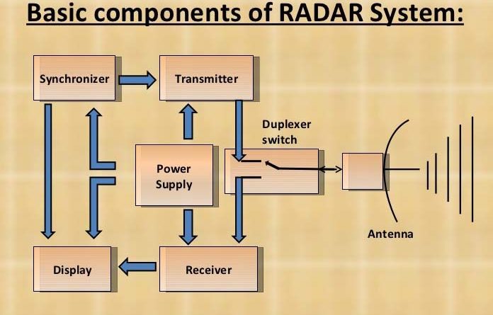
Radar Transmitter
A radar set has a blocking oscillator, a modulator, a pulse forming network, and a magnetron oscillator transmitter. The blocking oscillator circuit depends on the Cg and Rg values to determine how many times it operates. As the circuit start to oscillate, plate current (Ip) flows for an instance inducing a charge in Cg we’ beyond Ip cutoff. During the Ip off-time, Cg discharges slowly through Rg and the bias voltage decreases until finally Ip can begin to flow again. Circuit regeration develops a rapid rise in Ip.
These short duration 1p pulses induce high amplitude pulses in the grid winding of the transformer, the grid of the hydrogen thyratron (or an SCR) modulator is trigged by the positive pulse and the tube ionizes (Hydrogen ionizes and de-ionizes very rapidly). Ionization discharges the capacitors of the pulse forming network that have charged to 3000 V (3KV) through the charging reactor during the non-operating period of the oscillator. The discharge produces a narrow-square wave pulse of current through the primary of the pulse transformer, inducing high voltages in the secondaries. These two equal value voltages are in phase, rising the *cathode of the magnetron to a negative potential of several thousand volts above the magnetron plate. The average value of magnetron Ip, perhaps 2 to 5 mA, is indicated by the meter between ground and filament transformer. The square wave pulse of current from the pulse transformer excites electrons into oscillation in the cavities of the magnetron. These oscillations are coupled to the antenna and form the RF output burst.
Top 60 Electronics Websites & Blogs For Electrical & Electronic Engineers