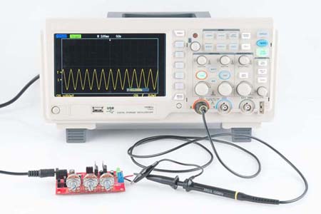
OSCILLOSCOPE
The oscilloscope is probably the most versatile and useful single instrument invented for electrical measurement work. It displays two dimensional graph of a signal. SP—e the oscilloscope uses no moving parts, it can handle signals thousands of tames faster than can mechanical plotters, recorders or meters.
OSCILLOSCOPE AND FIELDS OTHER THAN ELECTRONICS
Oscilloscope not only displays the voltage signals but other electrical and non electrical parameters can also be displayed using transducers. Transducers convert the physical phenomenon of interest into a physical quantity to a proportional voltage signal. This voltage signal represents the physical quantity of our interest. There are transducers for current, power, pressure, acceleration, temperature, displacement, strain, light and other physical quantities. This makes the oscilloscope a very useful tool in the field other than electronics.
Principle Of Working
It works not only on a single principle but it is a combination of MN several principles of basic sciences. Brief introduction of these principles is given below:
(i) Thermionic emission
This phenomenon was discovered by Thomas Edison in 1883 during his experiment on electric light bulbs. The librations of electrons from a hot surface is called thennionic emission. In oscilloscope a metal called cathode is heated to make the electrons to emit.
( ii) Electrostatic deflection
When an electron or a beam of electrons is passed between two plates providing electric field, it would behave in two ways:
(a) It would be attracted towards a positive plate.
(b) It would be repelled from a negative plate.
In this way in an oscilloscope, electron beam emitted from the cathode is deflected with the help of vertical and horizontal deflection & plates.
(iii) Fluorescence
The properly of a phosphor to emit light when its atoms arc excised is called fluorescence.
In Oscilloscope electron beam after deflection is made to strike a fluorescent screen. A light is emitted from spot when beam strikes.
(iv) Persistence of vision
The human eye retains an image for about 1/16 seconds after seeing it. This property of human eye is called persistence of vision. In an oscilloscope, the spot on the screen is moved so quickly that the path followed by the soot seems a solid line. If the beam moves on the same path at least 16 times in one second, the trace appears to the eye as a stable line.
Oscilloscope Basic Construction
Simplified block diagram of the basic oscilloscope is given. It has six basic sub-systems:
a) Calibrated attenuator
(b) Vertical amplifier
(c) Trigger circuit
(d) Time base circuit
(e) Horizontal amplifier
(f) CRT (cathode ray tube).
(a) Calibrated attenuator
The signal to be observed is fed to oscilloscope’s vertical input. It first passes through a calibrated input attenuator. It adjusts the vertical gain. The attenuator usually has a front-panel multi position switch calibrated in terms of volts/divisions.
(b) Vertical amplifiers
Then signal is magnified with the help of a vertical amplifier. This has fixed gain and a push-pull output stage which drives the vertical deflection plates with the required deflection voltage.
(c) Trigger circuit
For horizontal movement of beam, a circuit called trigger circuit is used. It initiates the sweep at a particular point in the waveform. It has two principal controls.
(i) Trigger level It selects the voltage at which the input signal initiates a sweep.
(ii) Slope It determines whether the sweep begins on the positive or negative going slope of waveform.
The combined effect of these controls permit the sweep to be triggered at any point in the waveform.
(d) Time base generator
It is the internal sweep generator of the oscilloscope. It provides a sawtooth waveform for the horizontal deflection of the trace. -The positive-going ramp of the sawtooth is linear. Slope of this waveform is controlled by lime/division front-panel control.
(e) Horizontal Amplifier
At the beginning of the ramp, the trace is automatically positioned at the left, of the screen. As the ramp voltage increases, the trace moves across the screen from left to right at a constant rate. At the end of the ramp, the trace is blanked and the trace rapidly returns to the left side of the screen and is ready for the next sweep to begin.
Horizontal amplifier The horizontal amplifier has a push pull output stage which drives the horizontal deflection plates. The input to the horizontal amplifier can he switched between two possible types of input signals. An external signal can he chosen as the input to the horizontal amplifier signal versus sweep voltage
(f) CATHODE RAY TUBE (CRT)
A CRT consists of an evacuated glass envelope. Construction of CRT is as below. It consists of the following parts
(i) Heated cathode (K)
(ii) Control grid (G)
(iii) First Accelerating anode (H)
(iv) Focusing electrode (F)
(v) Second accelerating anode (A)
(vi) Vertical deflection plates
(vii) Horizontal deflection plates
(viii) Phosphor screen
(ix) The Graticule
(x) Aquadag coating
(i) Heated cathode (K)
It is heated with the help of an enclosed filament and it starts emitting electrons.
(ii) Control Grid (G)
It is a cylinder with a small hole in its end for the passage of electrons. Its voltage is controlled with the help of front-panel INTENSITY. The more it is negative with respect to cathode, the fewer electrons will get through it and less intense is the trace appearing on the screen. In this way intensity is controlled with it)
(iii) First accelerating anode
It is also disc or a cylinder with a small hole in its centre. It is kept at a + ve voltage with respect to cathode t6 give acceleration to the electrons which have passed through control grid.
(iv) Focusing electrode(F)
Focal point of the electron beam is controlled by adjusting the voltage on the focusing electrode (F) with respect to the accelerating anode. This voltage is adjusted with the help of front-panel FOCUS control.
(v) Second accelerating anode(A)
After passing through focusing electrode, the electrons pass through a second accelerating anode. It is biased at the high positive voltage with respect to the cathode.
(vi) Vertical deflection plates
These are two plates. One plate is positively charged while other is negatively charged. The electron is attracted towards the positive plate and is repelled by the negative plate. As a result, electron beam is deflected between these plates. The amount of deflection is directly proportional to the voltage difference between the plates. Vertical amplifier provides this deflection voltage.
(vii) Horizontal deflection plates
These plates are same as that of the vertical deflection plates but they control the deflection of beam horizontally.
(viii) Phosphor screen
The beam of electrons finally strikes the phosphor coated screen which emits light. The property of a phosphor to emit light when its atoms are excite is called fluorescence. The property of a phosphor to continue emitting light, after the source of excitation is removed, is called phosphorescence)
(ix)The Graticule
A rectangular grid, called a graticule is placed on the screen of a CRT to provide accurate measurements of signal voltages and time periods.
(ix) Aquadag coating
The inside of the conical part of the CRT is coated with a conductive material called aquadag. It provides.
(a) Shielding from stray electromagnetic field.
(b) Prevents light from striking back of the screen.
(c) It gathers any secondary electrons emitted when the high velocity electrons of the beam strike the phosphor.