RADIO WAVE PROPAGATION
EM WAVE
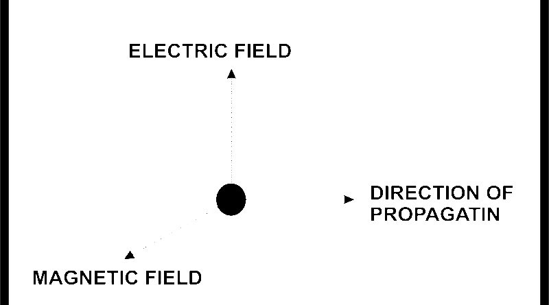
Em (electromagnetic) waves are space fields in which electric and magnetic fields at right angles to each other travel in a direction at right angles to both.
Electric field, magnetic field and direction of propagation are manually perpendicular to each other.
The wave consists of two components, electric field (E) and magnetic field (H), which travels with the speed of light in 4 free space and the direction of propagation is transverse (perpendicular) to the electric and magnetic field, which are already transverse to each other.
WAVE VELOCITY
Waves travel at various speeds, depending on the type of wave and the characteristics of the propagation medium. Sound waves travel at approximately 1100 ft/s in the normal atmosphere. Electromagnetic waves travel much faster. In free space (a vacuum), TEM wave travel at the speed of light, c =186,283 mi/s or 299,793,000 m/s , rounded off to 186,000 mi/s and 3+108 m/s . However, in air (such as earth is atmosphere), TEM waves travel slightly more slowly, and along a transmission line, electromagnetic waves travel considerably more slowly.
FREQUENCY AND WAVELENGHT
The oscillations of an electromagnetic wave are periodic and repetitive. Therefore, they are characterized by frequency. The rate at which the periodic wave repeats is its frequency. The distance of one cycle occurring in space is called the wavelength and is determined by the following fundamental equation:
Distance = velocity x time
λ = velocity x period
λ = v x T
and because
λ =1/f A = v/f
For free space propagation, v = c; therefore, the length of one cycle is
λ = c/f = 3×10⁸ m/s =meters / cycle
FIELD PATTERN OF EM WAVE
Field pattern of EM wave is Electromagnetic waves can be related to some extent to the waves produced in the water pond due to any disturbance. Waves developed in water pond are quite similar to electromagnetic waves except for one reason, whereas the water waves are longitudinal (i.e., oscillations are in the direction of propagation) , electromagnetic waves are transverse (oscillations perpendicular to the direction of propagation). Also the direction of magnetic field and the direction of electric field are mutually perpendicular to each other. The spatial relationships between the E and H fields of an electromagnetic wave.
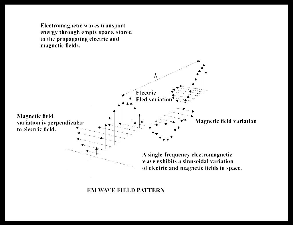
Electromagnetic waves transport energy through empty space, stored in the propagating electric and magnetic fields.
Magnetic field variation is perpendicular to electric field.
Electric Fled variation
Magnetic field variation
A single-frequency electromagnetic wave exhibits a sinusoidal variation of electric and magnetic fields in space.
EM WAVE FIELD PATTERN- PROPAGATION of E.M WAVE
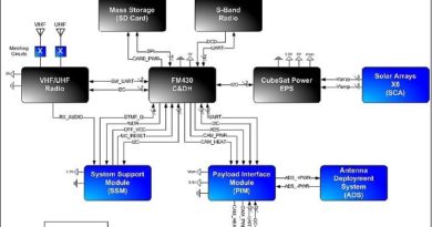
MASER
The name Maser stands for “Microwave amplification by stimulated emission of radiations”. It is a device that provides extremely low noise amplification of microwave signals by a quantum mechanical process. The maser based on quantum mechanical principal. The electrons belonging to the atoms of a substance can exist in various energy levels. At a very low temperature most of the electrons exist in the lowest energy level but they may be raised by the addition of specific amount of energy. Quantum theory shows that a quantum or bundle of energy may provide the required energy to raise the level of an electron, provided that
E=hf where
E= energy difference, Joules
F= proton frequency, Hz
H= Plank’s Constant (6.625)
Having been excited by the absorption of quantum, the atom may remain in the excited state, but this is most unlikely to last for more than perhaps a microsecond. It is far more likely that the photon of energy will be re-emitted, at the same frequency at which it was received, and the atom will thus return to its original, or grand state. The re-emission of energy has been stimulated at the expense of absorption.
It is then possible to make the atoms emit energy at a frequency corresponding to the difference between the top level and a level intermediate between the top level and the ground state and this process is done by the resonant structure. So pumping thus occurs at the frequency corresponding to the energy difference between the ground and the top energy levels. Re-emission of energy is stimulated at the desired frequency and the signal at this frequency is thus amplified. Practically no noise is added to the amplified signal.
Population Inversion Level 3 Top Level Signal Frequency Intermediate Level 2 Level 1 Pump Frequency Level Ground Level
The energy level situation in a three-level maser is illustrated. Energy is added at the pump frequency, raising electrons to the upper most of the level. Initially, the number of electrons in the third energy level is smaller than the number in the ground level, but as pumping is continues, the number of electrons in level 3 increases till it is nearly equal to the number in the first level. At this point, the crystal saturates and the so called population Inversion has been achieved.
Cavity Maser (Ruby Maser)
The Three-level maser may be operated in a cavity located within a cryostat consisting of a Dewar flask filled with liquid helium. The liquid helium is enclosed in a flask of liquid nitrogen to retard the evaporation of the helium.
The cryostat is placed between the pole pieces of a magnet. The cavity in which the paramagnetic maser material is located must be capable of supporting both the pump frequency and the signal frequency. The pump frequency is also known as saturation frequency. Pump power is supplied to the cavity via one transmission line, while the signal is inserted via another/ Since the cavity maser is a one port device, the amplified signal must be taken from the cavity via the same line through which it entered. A circulator separates the input signal from the amplified signal. Masers have been operated over almost the entire frequency band of interest to radar.,
Advantages The biggest advantage of a maser (Ruby maser) is its excellent noise performance. Noise of better than 0.3 dB is common. Bandwidths of about 25MHz at 1.5GHz are achieved with TW masers.
Disadvantages the main advantages is that it is a low level amplifier that would saturate with a few microvolt of power.
Applications
Maser are used where the received signals are very weak like house encountered in Radio Telescopes, Communication receivers used in conjunction with space borne probes and so on.