Sine Wave
Sine Wave: Sinusoidal Waveforms in AC Systems
Introduction to Sine Waves
The sine wave (or sinusoidal waveform) is the most fundamental and important waveform in electrical engineering and physics. It represents the purest form of alternating current (AC) and serves as the foundation for understanding all periodic phenomena in electrical systems.
From the electricity powering your home to the radio waves carrying your favorite music, sine waves are ubiquitous in modern technology. They are the natural output of rotating electrical generators, the basis for AC power distribution, and the building blocks for analyzing complex waveforms through Fourier analysis.
Understanding sine waves is essential because:
- AC Power Systems: All utility power is distributed as sine waves (50 Hz or 60 Hz)
- Signal Processing: Complex signals can be decomposed into sine wave components
- Communications: Radio, TV, and wireless signals use sine wave carriers
- Audio: Musical tones are sine waves or combinations of sine waves
- Circuit Analysis: Sine waves simplify AC circuit calculations using phasors
This comprehensive guide will explore every aspect of sine waves, from their mathematical foundations and physical generation to their properties, parameters, and practical applications in electrical engineering.
What is a Sine Wave?
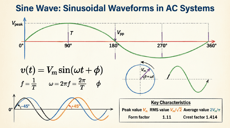
A sine wave is a smooth, periodic oscillation that follows the mathematical function y = A sin(ωt + φ), where A is amplitude, ω is angular frequency, t is time, and φ is phase angle. It represents the purest form of AC waveform and is the natural output of rotating electrical generators.
Mathematical Representation of Sine Waves
The Sine Function
A sine wave is mathematically described by the trigonometric sine function. The general equation for a sinusoidal voltage or current is:
$v(t) = V_m \sin(\omega t + \phi)$
Or for current:
$i(t) = I_m \sin(\omega t + \phi)$
Where:
- $v(t)$ or $i(t)$ = Instantaneous value at time t
- $V_m$ or $I_m$ = Maximum (peak) amplitude
- $\omega$ = Angular frequency in radians per second (rad/s)
- $t$ = Time in seconds (s)
- $\phi$ = Phase angle in radians or degrees
Alternative Forms
Using Frequency (f):
Since $\omega = 2\pi f$:
$v(t) = V_m \sin(2\pi f t + \phi)$
Using Period (T):
Since $f = 1/T$:
$v(t) = V_m \sin\left(\frac{2\pi t}{T} + \phi\right)$
Cosine Form:
Since $\cos(\theta) = \sin(\theta + 90°)$:
$v(t) = V_m \cos(\omega t + \phi’)$
Where $\phi’ = \phi – 90°$
Key Parameters Explained
1. Amplitude (A or V_m):
- Maximum displacement from zero
- Determines the “strength” or “loudness”
- Measured in volts (V), amperes (A), or other units
- Peak-to-peak amplitude: $V_{pp} = 2V_m$
2. Frequency (f):
- Number of complete cycles per second
- Measured in Hertz (Hz)
- Standard power frequencies: 50 Hz (Europe/Asia) or 60 Hz (North America)
- Audio range: 20 Hz to 20,000 Hz
- Radio frequencies: kHz to GHz
3. Period (T):
- Time for one complete cycle
- $T = \frac{1}{f}$
- Measured in seconds (s), milliseconds (ms), or microseconds (µs)
- Example: 60 Hz has $T = 1/60 = 16.67 \text{ ms}$
4. Angular Frequency (ω):
- Rate of change in radians per second
- $\omega = 2\pi f = \frac{2\pi}{T}$
- Measured in rad/s
- Example: 60 Hz has $\omega = 2\pi \times 60 = 377 \text{ rad/s}$
5. Phase Angle (φ):
- Horizontal shift of the waveform
- Measured in degrees (°) or radians (rad)
- Determines the starting point
- Positive φ: waveform shifted left (leads)
- Negative φ: waveform shifted right (lags)
What are the key parameters of a sine wave?
The five key parameters are: Amplitude (peak value), Frequency (cycles per second in Hz), Period (time for one cycle), Angular Frequency (radians per second), and Phase Angle (horizontal shift in degrees or radians).
Physical Generation of Sine Waves
Rotating Electrical Generators
The most common method of generating sine waves is through rotating electrical generators (alternators). This is how virtually all utility power is produced.
Principle of Operation:
- Faraday’s Law: When a conductor moves through a magnetic field, a voltage is induced
- Rotational Motion: A coil rotates at constant angular velocity in a uniform magnetic field
- Sinusoidal Output: The induced voltage varies sinusoidally with the angle of rotation
Mathematical Derivation:
For a coil rotating in a magnetic field:
- Magnetic flux: $\Phi = BA\cos(\theta)$
- Where θ = ωt (angle changes with time)
- Induced voltage: $v = -N\frac{d\Phi}{dt}$
- $v = -N\frac{d}{dt}[BA\cos(\omega t)]$
- $v = NBA\omega\sin(\omega t)$
- $v = V_m\sin(\omega t)$
Where:
- N = Number of turns in the coil
- B = Magnetic field strength
- A = Area of the coil
- ω = Angular velocity of rotation
- $V_m = NBA\omega$ = Peak voltage
Why Sine Wave?
The sine wave is the natural output because:
- The component of magnetic field perpendicular to the coil varies as cosine of the angle
- The rate of change (derivative) of cosine is sine
- Uniform rotation produces uniform angular velocity
Electronic Oscillators
For applications requiring precise frequency control or when mechanical generation is impractical, electronic oscillators generate sine waves:
Types of Oscillators:
- LC Oscillators:
- Use inductor (L) and capacitor (C) resonance
- Frequency: $f = \frac{1}{2\pi\sqrt{LC}}$
- Examples: Hartley, Colpitts, Clapp oscillators
- Used in radio transmitters
- Crystal Oscillators:
- Use piezoelectric quartz crystal
- Extremely stable frequency
- Used in clocks, computers, communications
- Accuracy: ±10 to ±100 ppm (parts per million)
- RC Oscillators:
- Use resistor-capacitor networks
- Lower frequencies (audio range)
- Examples: Wien bridge, Phase-shift oscillators
- Used in audio signal generators
- Function Generators:
- Digital synthesis (DDS – Direct Digital Synthesis)
- Programmable frequency and amplitude
- Used in test and measurement equipment
Natural Phenomena
Sine waves occur naturally in many physical systems:
Simple Harmonic Motion:
- Mass on a spring: $x(t) = A\sin(\omega t + \phi)$
- Pendulum (small angles)
- Vibrating strings (musical instruments)
Wave Motion:
- Sound waves in air
- Water waves
- Electromagnetic waves (light, radio)
AC Circuits:
- Voltage and current in RLC circuits at resonance
- Natural response of LC circuits
Properties and Characteristics of Sine Waves
Periodicity
Sine waves are periodic functions, meaning they repeat at regular intervals:
$v(t) = v(t + T)$
Where T is the period. This property is fundamental to AC power systems and signal processing.
Symmetry
Sine waves exhibit specific symmetries:
Odd Symmetry:
$\sin(-\theta) = -\sin(\theta)$
The waveform is symmetric about the origin (point symmetry).
Half-Wave Symmetry:
$\sin(\theta + \pi) = -\sin(\theta)$
The negative half-cycle is the mirror image of the positive half-cycle.
Orthogonality
Sine waves of different frequencies are orthogonal:
$\int_0^T \sin(n\omega t) \sin(m\omega t) dt = 0$ (for n ≠ m)
This property is the foundation of:
- Fourier series analysis
- Frequency division multiplexing
- Orthogonal Frequency Division Multiplexing (OFDM) in WiFi and 5G
Superposition
Multiple sine waves can be added together:
$v(t) = A_1\sin(\omega_1 t) + A_2\sin(\omega_2 t) + …$
This principle enables:
- Complex waveform synthesis
- Harmonic analysis
- Signal modulation
Derivative and Integral
Derivative:
$\frac{d}{dt}[A\sin(\omega t + \phi)] = A\omega\cos(\omega t + \phi)$
The derivative of a sine wave is a cosine wave (90° phase shift).
Integral:
$\int A\sin(\omega t + \phi) dt = -\frac{A}{\omega}\cos(\omega t + \phi) + C$
The integral is also a cosine wave, scaled by 1/ω.
RMS and Average Values
For a sine wave $v(t) = V_m\sin(\omega t)$:
RMS Value:
$V_{RMS} = \frac{V_m}{\sqrt{2}} = 0.7071V_m$
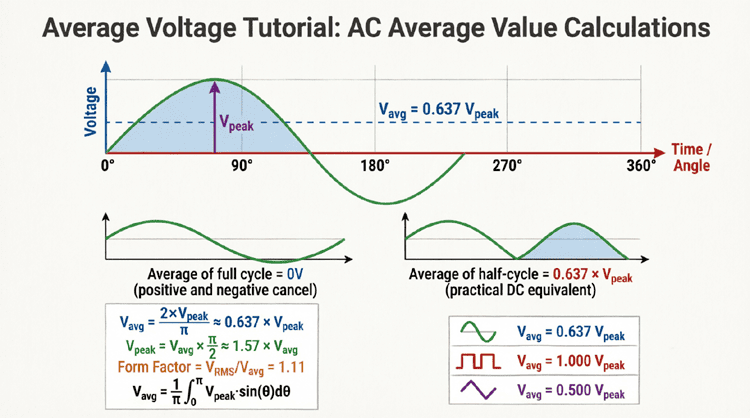
Average Value (Half-Cycle):
$V_{avg} = \frac{2V_m}{\pi} = 0.6366V_m$
Average Value (Full Cycle):
$V_{avg} = 0$ (positive and negative halves cancel)
Form Factor:
$FF = \frac{V_{RMS}}{V_{avg}} = \frac{\pi}{2\sqrt{2}} = 1.11$
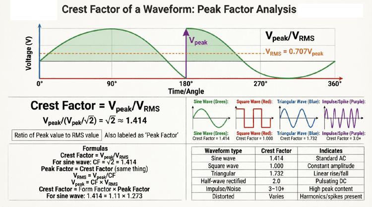
Crest Factor:
$CF = \frac{V_m}{V_{RMS}} = \sqrt{2} = 1.414$
What is the RMS value of a sine wave?
The RMS (root mean square) value of a sine wave is V_m/√2 ≈ 0.7071 × V_m, where V_m is the peak amplitude. For example, a sine wave with 170V peak has an RMS value of 120V, which is the standard household voltage in North America.
Sine Wave Parameters in AC Power Systems
Standard Power Frequencies
50 Hz Systems:
- Used in: Europe, Asia, Africa, Australia, most of the world
- Period: T = 1/50 = 20 ms
- Angular frequency: ω = 2π × 50 = 314 rad/s
- Generator speed: 3000 RPM (2-pole) or 1500 RPM (4-pole)
60 Hz Systems:
- Used in: North America, parts of South America, Japan (some regions)
- Period: T = 1/60 = 16.67 ms
- Angular frequency: ω = 2π × 60 = 377 rad/s
- Generator speed: 3600 RPM (2-pole) or 1800 RPM (4-pole)
Voltage Levels
Residential (Single-Phase):
- North America: 120V RMS (170V peak), 240V RMS for large appliances
- Europe/Asia: 230V RMS (325V peak)
Industrial (Three-Phase):
- North America: 208V, 480V, 600V line-to-line
- Europe/Asia: 400V, 690V line-to-line
Transmission:
- Distribution: 4 kV to 35 kV
- Sub-transmission: 69 kV to 138 kV
- High voltage: 230 kV to 500 kV
- Extra-high voltage: 765 kV and above
Phase Relationships in Three-Phase Systems
Three-phase power uses three sine waves separated by 120°:
Phase A: $v_a(t) = V_m\sin(\omega t)$
Phase B: $v_b(t) = V_m\sin(\omega t – 120°)$
Phase C: $v_c(t) = V_m\sin(\omega t – 240°) = V_m\sin(\omega t + 120°)$
Advantages:
- Constant power transfer (no pulsations)
- More efficient than single-phase
- Self-starting motors
- Smaller conductors for same power
Sine Waves vs. Other Waveforms
Comparison with Common Waveforms
| Parameter | Sine Wave | Square Wave | Triangle Wave | Sawtooth Wave |
|---|---|---|---|---|
| RMS Value | 0.707V_m | V_m | 0.577V_m | 0.577V_m |
| Average (½ cycle) | 0.637V_m | V_m | 0.5V_m | 0.5V_m |
| Form Factor | 1.11 | 1.0 | 1.155 | 1.155 |
| Crest Factor | 1.414 | 1.0 | 1.732 | 1.732 |
| Harmonics | None (pure) | Odd only | Odd only | All |
| Generation | Natural | Switching | Integration | Integration |
Why Sine Waves Dominate AC Power
1. Efficient Generation:
- Rotating machines naturally produce sine waves
- No additional conversion needed
- Smooth torque in motors
2. Efficient Transmission:
- Minimal harmonic losses
- Lower skin effect than square waves
- Reduced electromagnetic interference
3. Transformer Compatibility:
- Sine waves magnetize cores efficiently
- No saturation from harmonics
- Lower core losses
4. Motor Performance:
- Smooth torque production
- Minimal vibration and noise
- Higher efficiency
5. Mathematical Simplicity:
- Phasor analysis simplifies calculations
- Derivatives and integrals remain sinusoidal
- Linear systems preserve sine wave shape
Fourier Series: Building Complex Waveforms
Any periodic waveform can be expressed as a sum of sine waves:
$f(t) = A_0 + \sum_{n=1}^{\infty} [A_n\sin(n\omega t) + B_n\cos(n\omega t)]$
Where:
- $A_0$ = DC component
- $A_n, B_n$ = Amplitudes of harmonic components
- $n\omega$ = Harmonic frequencies (2ω, 3ω, 4ω, …)
Example: Square Wave
A square wave can be synthesized from odd harmonics:
$v(t) = \frac{4V_m}{\pi}[\sin(\omega t) + \frac{1}{3}\sin(3\omega t) + \frac{1}{5}\sin(5\omega t) + …]$
This demonstrates that sine waves are the fundamental building blocks of all periodic signals.
Practical Applications of Sine Waves
1. AC Power Distribution
Utility Power:
- All grid electricity is sine wave AC
- Enables efficient long-distance transmission
- Easy voltage transformation with transformers
- Standard frequencies: 50 Hz or 60 Hz
Benefits:
- Transformers only work with AC (changing magnetic field)
- Sine waves minimize losses and interference
- Motors and generators designed for sinusoidal operation
2. Audio and Music
Musical Tones:
- Pure tones are sine waves
- Musical instruments produce combinations of sine waves (harmonics)
- Human voice: complex waveform of multiple sine components
Audio Engineering:
- Test tones for equipment calibration
- Sine wave sweeps for frequency response measurement
- Synthesis and sound design
Example: A 440 Hz sine wave is the musical note A4 (standard tuning pitch).
3. Radio and Communications
Carrier Waves:
- Radio transmitters use sine wave carriers
- Modulation techniques:
- AM (Amplitude Modulation): Vary amplitude
- FM (Frequency Modulation): Vary frequency
- PM (Phase Modulation): Vary phase
Frequency Bands:
- AM Radio: 530-1700 kHz
- FM Radio: 88-108 MHz
- WiFi: 2.4 GHz and 5 GHz
- 5G: Sub-6 GHz and mmWave (24-100 GHz)
4. Signal Processing
Filter Design:
- Low-pass, high-pass, band-pass filters
- Frequency-selective circuits
- Sine wave response characterizes filter behavior
Spectrum Analysis:
- FFT (Fast Fourier Transform) decomposes signals into sine components
- Identifies frequency content
- Essential for troubleshooting and design
5. Test and Measurement
Function Generators:
- Produce precise sine waves for testing
- Variable frequency and amplitude
- Used in circuit characterization
Oscilloscopes:
- Display sine waveforms
- Measure amplitude, frequency, phase
- Analyze distortion and harmonics
6. Control Systems
AC Motor Drives:
- Variable Frequency Drives (VFDs) synthesize sine waves
- Control motor speed by varying frequency
- PWM (Pulse Width Modulation) approximates sine waves
Inverters:
- Convert DC to AC (sine wave)
- Solar panel inverters
- UPS (Uninterruptible Power Supply) systems
Practical Examples and Calculations
Example 1: Sine Wave Parameter Calculation
Problem: A sine wave voltage is given by $v(t) = 325\sin(377t + 30°)$ V. Determine:
- Peak voltage
- RMS voltage
- Frequency
- Period
- Phase angle
Solution:
Comparing to standard form $v(t) = V_m\sin(\omega t + \phi)$:
1. Peak Voltage:
$V_m = 325\text{V}$
2. RMS Voltage:
$V_{RMS} = \frac{V_m}{\sqrt{2}} = \frac{325}{1.414} = 229.8\text{V} \approx 230\text{V}$
3. Frequency:
$\omega = 377 \text{ rad/s}$
$f = \frac{\omega}{2\pi} = \frac{377}{2\pi} = \frac{377}{6.283} = 60\text{ Hz}$
4. Period:
$T = \frac{1}{f} = \frac{1}{60} = 0.01667\text{s} = 16.67\text{ ms}$
5. Phase Angle:
$\phi = 30°$ (leads reference by 30°)
Result: This is a standard 230V RMS, 60 Hz sine wave with a 30° phase lead.
Example 2: Time-Domain Calculation
Problem: For the sine wave $v(t) = 170\sin(377t)$ V, calculate the instantaneous voltage at:
- t = 0 ms
- t = 2.08 ms
- t = 4.17 ms
- t = 8.33 ms
Solution:
Given: $v(t) = 170\sin(377t)$
At t = 0 ms:
$v(0) = 170\sin(377 \times 0) = 170\sin(0) = 170 \times 0 = 0\text{V}$
At t = 2.08 ms = 0.00208 s:
$v(0.00208) = 170\sin(377 \times 0.00208)$
$= 170\sin(0.784) = 170\sin(44.9°)$
$= 170 \times 0.707 = 120\text{V}$
At t = 4.17 ms = 0.00417 s:
$v(0.00417) = 170\sin(377 \times 0.00417)$
$= 170\sin(1.57) = 170\sin(90°)$
$= 170 \times 1.0 = 170\text{V}$ (peak!)
At t = 8.33 ms = 0.00833 s:
$v(0.00833) = 170\sin(377 \times 0.00833)$
$= 170\sin(3.14) = 170\sin(180°)$
$= 170 \times 0 = 0\text{V}$
Interpretation: These times correspond to 0°, 45°, 90°, and 180° of the cycle.
Example 3: Phase Difference Calculation
Problem: Two voltages are given by:
$v_1(t) = 100\sin(377t + 45°)$ V
$v_2(t) = 150\sin(377t – 30°)$ V
Calculate:
- The phase difference between them
- Which voltage leads?
- The time difference corresponding to the phase difference
Solution:
1. Phase Difference:
$\Delta\phi = \phi_1 – \phi_2 = 45° – (-30°) = 75°$
2. Leading Voltage:
$v_1$ has phase +45°, $v_2$ has phase -30°
$v_1$ leads $v_2$ by 75°
3. Time Difference:
Frequency: $f = \frac{377}{2\pi} = 60\text{ Hz}$
Period: $T = \frac{1}{60} = 16.67\text{ ms}$
Time for 75°:
$\Delta t = \frac{75°}{360°} \times T = \frac{75}{360} \times 16.67\text{ ms}$
$\Delta t = 0.2083 \times 16.67\text{ ms} = 3.47\text{ ms}$
Result: $v_1$ leads $v_2$ by 75°, which corresponds to 3.47 ms at 60 Hz.
Summary and Conclusion
The sine wave is the cornerstone of AC electrical systems and signal processing. Its mathematical elegance, physical realizability, and unique properties make it the natural choice for power distribution, communications, and countless other applications.
Key takeaways from this comprehensive guide include:
- Mathematical Foundation:
- General form: $v(t) = V_m\sin(\omega t + \phi)$
- Five key parameters: amplitude, frequency, period, angular frequency, and phase angle
- Derivatives and integrals remain sinusoidal
- Physical Generation:
- Rotating generators naturally produce sine waves via Faraday’s law
- Electronic oscillators provide precise frequency control
- Occurs naturally in harmonic motion and wave phenomena
- Essential Properties:
- Periodicity: repeats every period T
- Symmetry: odd function with half-wave symmetry
- Orthogonality: different frequencies are independent
- RMS = 0.707 × peak, Average = 0.637 × peak (half-cycle)
- AC Power Systems:
- Standard frequencies: 50 Hz (most of world) or 60 Hz (North America)
- Residential voltages: 120V or 230V RMS
- Three-phase systems use three sine waves 120° apart
- Advantages Over Other Waveforms:
- Efficient generation and transmission
- Minimal harmonic losses
- Compatible with transformers and motors
- Mathematical simplicity for analysis
- Applications:
- AC power distribution (utility grid)
- Audio and music (pure tones, harmonics)
- Radio communications (carrier waves)
- Signal processing (Fourier analysis)
- Test and measurement (function generators)
- Fourier Series:
- Any periodic waveform can be decomposed into sine wave components
- Sine waves are the fundamental building blocks of all periodic signals
- Enables frequency-domain analysis
Understanding sine waves is fundamental to mastering AC circuit theory, power systems, signal processing, and communications. Whether you’re analyzing a simple RLC circuit, designing a power distribution system, troubleshooting audio equipment, or developing wireless communications, the sine wave provides the essential framework for understanding and manipulating electrical signals.
As you continue your electrical engineering journey, remember that the sine wave is not just a mathematical abstraction—it is the physical reality of how we generate, transmit, and utilize electrical energy in the modern world. Mastery of sine wave concepts opens the door to understanding everything from the power in your home to the signals carrying your favorite music and videos across the globe.