Form Factor of a Waveform
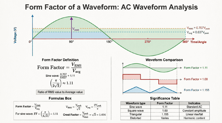
Form Factor of a Waveform: AC Waveform Analysis
Introduction to Form Factor
When analyzing alternating current (AC) waveforms, engineers need more than just peak or RMS values to fully characterize the waveform’s behavior. Form factor is a crucial parameter that reveals the relationship between a waveform’s RMS (root mean square) value and its average value, providing insights into the waveform’s shape and characteristics.
Form factor is particularly important in:
- Designing and calibrating AC measuring instruments
- Analyzing rectifier circuits and power supplies
- Evaluating waveform distortion
- Comparing different waveform shapes
- Understanding the heating effects of various waveforms
While the concept may seem abstract, form factor has practical implications in electrical engineering. For instance, analog multimeters that measure average values but display RMS readings rely on the form factor of a sine wave (1.11) for their calibration. When the waveform deviates from a pure sine wave, these meters give incorrect readings—a direct consequence of form factor variation.
This comprehensive guide will explore form factor from every angle, including its mathematical derivation, values for different waveform shapes, relationship to crest factor, and practical applications in electrical measurements and power systems.
What is Form Factor?
Form factor is the ratio of the RMS (root mean square) value to the average value of a waveform. For a pure sine wave, the form factor is 1.11 (or π/(2√2)). It indicates how “peaky” or “flat” a waveform is compared to its average value.
Understanding Form Factor: Definition and Significance
Mathematical Definition
Form Factor (FF) is defined as the ratio of the RMS value to the average value (measured over a half-cycle for symmetrical AC waveforms):
$FF = \frac{V_{RMS}}{V_{avg}}$
Or for current:
$FF = \frac{I_{RMS}}{I_{avg}}$
Where:
- $V_{RMS}$ = RMS (effective) value of the waveform
- $V_{avg}$ = Average value (half-cycle average for AC)
- FF = Form factor (dimensionless)
Why Form Factor Matters
Form factor provides critical information about a waveform:
1. Waveform Shape Indicator:
- Different waveform shapes have different form factors
- Deviations from expected form factor indicate distortion
- Helps identify waveform anomalies
2. Instrument Calibration:
- Analog AC meters are calibrated assuming a specific form factor (1.11 for sine waves)
- Measuring non-sinusoidal waveforms with these meters gives errors
- True RMS meters are needed for accurate measurements of distorted waveforms
3. Power Calculations:
- Relates to the heating effect of the waveform
- Important for sizing conductors and protective devices
- Affects transformer and motor performance
4. Rectifier Design:
- Determines the DC output quality
- Affects filter capacitor sizing
- Influences ripple factor calculations
Relationship to Other Waveform Parameters
Form factor is one of several dimensionless parameters used to characterize waveforms:
1. Crest Factor (Peak Factor):
$CF = \frac{V_{peak}}{V_{RMS}}$
2. Ripple Factor:
$RF = \sqrt{FF^2 – 1}$ (for rectified waveforms)
3. Duty Cycle:
For pulse waveforms, affects both RMS and average values
These parameters together provide a complete picture of waveform characteristics.
What is the form factor of a pure sine wave?
The form factor of a pure sine wave is 1.11 (or more precisely, π/(2√2) ≈ 1.1107). This means the RMS value is 1.11 times the half-cycle average value. This constant is used to calibrate analog AC voltmeters and ammeters.
Form Factor of a Sine Wave
Derivation for Sinusoidal Waveform
Let’s derive the form factor for a pure sine wave step by step.
Given a sinusoidal voltage:
$v(t) = V_m \sin(\omega t)$
Where $V_m$ is the peak (maximum) voltage.
Step 1: Calculate RMS Value
For a sine wave, the RMS value is:
$V_{RMS} = \frac{V_m}{\sqrt{2}} = 0.7071 V_m$
Step 2: Calculate Average Value (Half-Cycle)
The average value over a half-cycle (0 to π) is:
$V_{avg} = \frac{1}{\pi} \int_0^\pi V_m \sin(\theta) d\theta$
$V_{avg} = \frac{V_m}{\pi} [-\cos(\theta)]_0^\pi$
$V_{avg} = \frac{V_m}{\pi} [-\cos(\pi) – (-\cos(0))]$
$V_{avg} = \frac{V_m}{\pi} [1 + 1] = \frac{2V_m}{\pi}$
$V_{avg} = 0.6366 V_m$
Step 3: Calculate Form Factor
$FF = \frac{V_{RMS}}{V_{avg}} = \frac{V_m/\sqrt{2}}{2V_m/\pi}$
$FF = \frac{\pi}{2\sqrt{2}} = \frac{3.14159}{2 \times 1.4142}$
$FF = 1.1107 \approx 1.11$
Practical Implications
The form factor of 1.11 for sine waves has several important implications:
1. Analog Meter Calibration:
- Moving-coil meters with rectifiers measure average value
- Scale is multiplied by 1.11 to display RMS
- Accurate only for pure sine waves
2. Relationship Verification:
If you measure both RMS and average values:
- $V_{RMS} = 1.11 \times V_{avg}$ confirms sine wave
- Deviation indicates distortion or different waveform
3. Power Calculations:
For a sine wave with known average value:
- $V_{RMS} = 1.11 \times V_{avg}$
- $P = \frac{V_{RMS}^2}{R} = \frac{(1.11 \times V_{avg})^2}{R}$
Example: Sine Wave Form Factor Calculation
Problem: A sinusoidal voltage has a peak value of 325V. Calculate the RMS value, average value, and verify the form factor.
Solution:
Given: $V_m = 325V$
Calculate RMS:
$V_{RMS} = \frac{325}{\sqrt{2}} = \frac{325}{1.4142} = 229.8V \approx 230V$
Calculate Average:
$V_{avg} = \frac{2 \times 325}{\pi} = \frac{650}{3.14159} = 206.9V$
Verify Form Factor:
$FF = \frac{V_{RMS}}{V_{avg}} = \frac{229.8}{206.9} = 1.111$
Result: FF ≈ 1.11 ✓ (confirms sine wave)
Form Factor for Different Waveform Shapes
Different waveform shapes have different form factors. Understanding these variations is crucial for accurate measurements and analysis.
1. Square Wave
Characteristics:
- Constant amplitude
- Instantaneous transitions
- 50% duty cycle (symmetrical)
Values:
- $V_{RMS} = V_m$ (same as peak)
- $V_{avg} = V_m$ (half-cycle average)
Form Factor:
$FF = \frac{V_{RMS}}{V_{avg}} = \frac{V_m}{V_m} = 1.0$
Interpretation: A square wave has the lowest possible form factor, indicating maximum “flatness.”
2. Triangle Wave
Characteristics:
- Linear rise and fall
- Symmetrical waveform
Values:
- $V_{RMS} = \frac{V_m}{\sqrt{3}} = 0.577 V_m$
- $V_{avg} = \frac{V_m}{2} = 0.5 V_m$
Form Factor:
$FF = \frac{V_m/\sqrt{3}}{V_m/2} = \frac{2}{\sqrt{3}} = 1.155$
Interpretation: Slightly higher than sine wave, indicating a more “peaky” shape.
3. Sawtooth Wave
Characteristics:
- Linear rise, instantaneous fall (or vice versa)
- Asymmetrical
Values:
- $V_{RMS} = \frac{V_m}{\sqrt{3}} = 0.577 V_m$
- $V_{avg} = \frac{V_m}{2} = 0.5 V_m$
Form Factor:
$FF = \frac{2}{\sqrt{3}} = 1.155$
Note: Same as triangle wave for symmetrical sawtooth.
4. Half-Wave Rectified Sine Wave
Characteristics:
- Only positive half-cycles
- Zero during negative half-cycles
Values:
- $V_{RMS} = \frac{V_m}{2} = 0.5 V_m$
- $V_{avg} = \frac{V_m}{\pi} = 0.318 V_m$
Form Factor:
$FF = \frac{V_m/2}{V_m/\pi} = \frac{\pi}{2} = 1.571$
Interpretation: Much higher than sine wave due to the zero portions.
5. Full-Wave Rectified Sine Wave
Characteristics:
- Both half-cycles converted to positive
- No zero portions
Values:
- $V_{RMS} = \frac{V_m}{\sqrt{2}} = 0.707 V_m$
- $V_{avg} = \frac{2V_m}{\pi} = 0.637 V_m$
Form Factor:
$FF = \frac{V_m/\sqrt{2}}{2V_m/\pi} = \frac{\pi}{2\sqrt{2}} = 1.11$
Note: Same as sine wave (makes sense, as it’s just the absolute value).
6. Pulse Wave (Variable Duty Cycle)
Characteristics:
- Rectangular pulses
- Duty cycle D (fraction of period where signal is high)
Values:
- $V_{RMS} = V_m \sqrt{D}$
- $V_{avg} = V_m \times D$
Form Factor:
$FF = \frac{V_m \sqrt{D}}{V_m D} = \frac{1}{\sqrt{D}}$
Examples:
- D = 50% (0.5): $FF = \frac{1}{\sqrt{0.5}} = 1.414$
- D = 25% (0.25): $FF = \frac{1}{\sqrt{0.25}} = 2.0$
- D = 10% (0.1): $FF = \frac{1}{\sqrt{0.1}} = 3.162$
Interpretation: Lower duty cycles produce higher form factors.
Comparison Table
| Waveform | RMS Value | Average Value | Form Factor |
|---|---|---|---|
| Sine Wave | 0.707 $V_m$ | 0.637 $V_m$ | 1.11 |
| Square Wave | 1.0 $V_m$ | 1.0 $V_m$ | 1.0 |
| Triangle Wave | 0.577 $V_m$ | 0.5 $V_m$ | 1.155 |
| Sawtooth Wave | 0.577 $V_m$ | 0.5 $V_m$ | 1.155 |
| Half-Wave Rectified | 0.5 $V_m$ | 0.318 $V_m$ | 1.571 |
| Full-Wave Rectified | 0.707 $V_m$ | 0.637 $V_m$ | 1.11 |
| Pulse (50% duty) | 0.707 $V_m$ | 0.5 $V_m$ | 1.414 |
Which waveform has the lowest form factor?
A square wave has the lowest form factor of 1.0, because its RMS value equals its average value. This indicates the most “efficient” waveform in terms of delivering constant amplitude.
Form Factor vs. Crest Factor
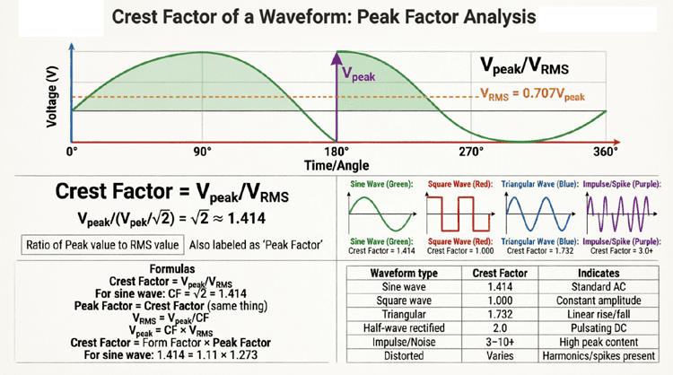
While form factor compares RMS to average value, crest factor (also called peak factor) compares peak to RMS value. Both are important for characterizing waveforms.
Crest Factor Definition
$CF = \frac{V_{peak}}{V_{RMS}}$
Comparison of Form Factor and Crest Factor
| Parameter | Formula | Sine Wave | Square Wave | Triangle Wave |
|---|---|---|---|---|
| Form Factor | $V_{RMS}/V_{avg}$ | 1.11 | 1.0 | 1.155 |
| Crest Factor | $V_{peak}/V_{RMS}$ | 1.414 | 1.0 | 1.732 |
Key Differences
Form Factor:
- Indicates waveform “flatness” vs. “peakiness”
- Important for average-responding meters
- Relates to DC component after rectification
Crest Factor:
- Indicates peak amplitude relative to heating effect
- Important for insulation design
- Critical for avoiding clipping and distortion
- Affects dynamic range requirements
Relationship
For a sine wave:
- $FF = 1.11$
- $CF = 1.414$
- $FF \times CF = 1.11 \times 1.414 = 1.57 \approx \frac{\pi}{2}$
This relationship varies for different waveforms.
Practical Applications of Form Factor
1. Analog AC Meter Design
Moving-Coil Meter with Rectifier:
Most analog multimeters use a moving-coil (D’Arsonval) movement, which responds to average current. To measure AC:
- Rectification: Diodes convert AC to pulsating DC
- Average Measurement: Meter measures average value
- Scale Calibration: Scale is multiplied by 1.11 to display RMS
Problem: This works only for sine waves!
Example Error:
If you measure a square wave with an average-responding meter:
- Meter reads: $V_{avg} \times 1.11$
- Actual RMS: $V_{peak}$
- For square wave: $V_{avg} = V_{peak}$
- Meter displays: $V_{peak} \times 1.11$
- Error: +11% high!
Solution: Use True RMS meters for non-sinusoidal waveforms.
2. Rectifier Circuit Analysis
Ripple Factor Calculation:
The ripple factor indicates the quality of DC output from a rectifier:
$RF = \sqrt{FF^2 – 1}$
For half-wave rectified sine wave:
$RF = \sqrt{1.571^2 – 1} = \sqrt{2.468 – 1} = \sqrt{1.468} = 1.21$
High ripple factor indicates poor DC quality, requiring larger filter capacitors.
3. Transformer and Motor Design
Heating Effects:
Form factor affects the heating in transformers and motors:
- Higher form factor → higher RMS for same average
- More heating for same average current
- Requires larger conductors or better cooling
Design Consideration:
Equipment designed for sine waves (FF = 1.11) may overheat with distorted waveforms (higher FF).
4. Power Quality Analysis
Waveform Distortion Detection:
By measuring both RMS and average values:
- Calculate actual form factor
- Compare to expected value (1.11 for sine)
- Deviation indicates distortion or harmonics
Example:
- Measured $V_{RMS} = 120V$
- Measured $V_{avg} = 100V$
- Calculated $FF = 120/100 = 1.2$
- Expected FF = 1.11
- Conclusion: Waveform is distorted (likely harmonics present)
Practical Examples and Calculations
Example 1: Form Factor of a Triangle Wave
Problem: A triangle wave has a peak voltage of 100V. Calculate the RMS value, average value, and form factor.
Solution:
Given: $V_m = 100V$
For a triangle wave:
RMS Value:
$V_{RMS} = \frac{V_m}{\sqrt{3}} = \frac{100}{1.732} = 57.74V$
Average Value:
$V_{avg} = \frac{V_m}{2} = \frac{100}{2} = 50V$
Form Factor:
$FF = \frac{V_{RMS}}{V_{avg}} = \frac{57.74}{50} = 1.155$
Verification:
$FF = \frac{2}{\sqrt{3}} = 1.155$ ✓
Example 2: Meter Reading Error
Problem: An average-responding AC voltmeter (calibrated for sine waves) is used to measure a 10V peak square wave. What will the meter read, and what is the percentage error?
Solution:
Given: Square wave, $V_m = 10V$
Actual Values for Square Wave:
- $V_{RMS} = V_m = 10V$
- $V_{avg} = V_m = 10V$
- Form Factor = 1.0
Meter Reading:
The meter measures average and multiplies by 1.11:
$V_{display} = V_{avg} \times 1.11 = 10 \times 1.11 = 11V$
Error:
$Error = V_{display} – V_{actual} = 11 – 10 = 1V$
$\% Error = \frac{1}{10} \times 100\% = +10\%$
Result: The meter reads 10% high!
Example 3: Determining Waveform Type
Problem: A waveform has an RMS value of 70.7V and an average value of 63.7V. Determine the form factor and identify the likely waveform type.
Solution:
Given:
- $V_{RMS} = 70.7V$
- $V_{avg} = 63.7V$
Calculate Form Factor:
$FF = \frac{70.7}{63.7} = 1.11$
Identify Waveform:
Form factor of 1.11 indicates:
- Sine wave (most likely)
- Or full-wave rectified sine wave
Verify:
If sine wave:
- $V_m = V_{RMS} \times \sqrt{2} = 70.7 \times 1.414 = 100V$
- $V_{avg} = \frac{2 \times 100}{\pi} = 63.66V$ ≈ 63.7V ✓
Conclusion: This is a sine wave with $V_m ≈ 100V$.
Summary and Conclusion
Form factor is a fundamental parameter in AC waveform analysis that reveals the relationship between RMS and average values. While seemingly simple, it has profound implications for electrical measurements, instrument design, and power system analysis.
Key takeaways from this guide include:
- Definition: Form factor = RMS value / Average value (dimensionless)
- Sine Wave: FF = 1.11 (π/(2√2)) – the standard for AC power systems
- Waveform Comparison:
- Square wave: FF = 1.0 (lowest)
- Sine wave: FF = 1.11
- Triangle/Sawtooth: FF = 1.155
- Half-wave rectified: FF = 1.571
- Pulse waves: FF = 1/√D (varies with duty cycle)
- Measurement Implications:
- Average-responding meters assume FF = 1.11
- Non-sinusoidal waveforms cause measurement errors
- True RMS meters are essential for distorted waveforms
- Practical Applications:
- Instrument calibration and design
- Rectifier circuit analysis
- Power quality assessment
- Transformer and motor design
- Relationship to Crest Factor:
- Form factor: RMS/Average (indicates flatness)
- Crest factor: Peak/RMS (indicates peakiness)
- Both needed for complete waveform characterization
Understanding form factor enables engineers to:
- Select appropriate measurement instruments
- Design accurate calibration systems
- Analyze waveform distortion
- Optimize power conversion circuits
- Ensure proper equipment sizing
Whether you’re designing a power supply, troubleshooting a motor drive, or calibrating test equipment, form factor provides essential insights into waveform behavior that peak and RMS values alone cannot reveal. Mastering this concept is crucial for anyone working with AC power systems, signal processing, or electrical measurements.