Impedance and Complex Impedance
Impedance and Complex Impedance: AC Circuit Analysis
Introduction to Impedance
In the realm of alternating current (AC) circuits, impedance is the fundamental concept that extends Ohm’s Law beyond simple DC resistance. While resistance opposes current flow uniformly in both DC and AC circuits, impedance represents the total opposition to AC current, combining both resistance and reactance into a single, comprehensive quantity.
Understanding impedance is crucial because it allows engineers to:
- Analyze complex AC circuits using familiar DC techniques
- Calculate voltage drops and current flow in RLC networks
- Design filters and matching networks
- Predict circuit behavior across different frequencies
- Simplify power calculations
What makes impedance particularly powerful is its representation as a complex number. This mathematical framework allows us to handle both the magnitude of opposition (how much) and the phase shift (when) simultaneously, transforming complicated trigonometric calculations into straightforward algebraic operations.
This comprehensive guide will explore impedance from every angle—from basic definitions to advanced complex number representations, polar and rectangular forms, and practical circuit analysis techniques. Whether you’re designing audio equipment, analyzing power systems, or troubleshooting electronic circuits, mastering impedance is essential for success.
What is Impedance?
Impedance (Z) is the total opposition to alternating current flow in an AC circuit, combining both resistance (R) and reactance (X). It is measured in ohms (Ω) and represented as a complex number: Z = R + jX, where R is resistance and X is reactance (inductive or capacitive).
Understanding Impedance: Resistance vs. Reactance
The Two Components of Impedance
Impedance consists of two distinct components that affect AC current differently:
1. Resistance (R) – The Real Component
- Opposes current flow uniformly at all frequencies
- Dissipates energy as heat
- Causes no phase shift between voltage and current
- Represented on the real axis of the complex plane
- Measured in ohms (Ω)
2. Reactance (X) – The Imaginary Component
- Opposes changes in current or voltage
- Stores and releases energy (doesn’t dissipate)
- Causes a 90° phase shift
- Represented on the imaginary axis of the complex plane
- Measured in ohms (Ω)
- Can be inductive (+jX) or capacitive (-jX)
Inductive Reactance vs. Capacitive Reactance
Inductive Reactance ($X_L$):
- Caused by inductors (coils, transformers, motors)
- Increases with frequency: $X_L = 2\pi f L$
- Voltage leads current by 90°
- Represented as +jX_L (positive imaginary)
- Example: A 10 mH inductor at 60 Hz has $X_L = 3.77 \Omega$
Capacitive Reactance ($X_C$):
- Caused by capacitors
- Decreases with frequency: $X_C = \frac{1}{2\pi f C}$
- Current leads voltage by 90°
- Represented as -jX_C (negative imaginary)
- Example: A 10 μF capacitor at 60 Hz has $X_C = 265 \Omega$
Net Reactance
When both inductors and capacitors are present in a circuit, their reactances oppose each other:
$X_{net} = X_L – X_C$
- If $X_L > X_C$: Net reactance is inductive (positive)
- If $X_C > X_L$: Net reactance is capacitive (negative)
- If $X_L = X_C$: Net reactance is zero (resonance condition)
What is the difference between resistance and reactance?
Resistance (R) opposes current uniformly and dissipates energy as heat with no phase shift. Reactance (X) opposes changes in current/voltage, stores energy in magnetic or electric fields, and causes a 90° phase shift. Resistance is frequency-independent; reactance varies with frequency.
Complex Impedance Representation
The Complex Number System
Complex impedance uses the mathematical framework of complex numbers to represent both magnitude and phase in a single quantity. A complex number has two parts:
Rectangular Form:
$Z = R + jX$
Where:
- R = Real part (resistance)
- j = Imaginary unit ($\sqrt{-1}$)
- X = Imaginary part (reactance)
Why “j” instead of “i”?
In mathematics, the imaginary unit is denoted as “i”. However, in electrical engineering, “i” represents instantaneous current. To avoid confusion, engineers use “j” for the imaginary unit.
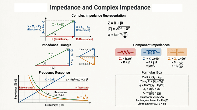
Visualizing Complex Impedance
Complex impedance can be visualized on the complex plane (also called the Argand diagram):
- Horizontal axis (Real axis): Resistance (R)
- Vertical axis (Imaginary axis): Reactance (X)
- Positive imaginary direction (up): Inductive reactance (+jX_L)
- Negative imaginary direction (down): Capacitive reactance (-jX_C)
The impedance vector extends from the origin (0,0) to the point (R, X), forming the hypotenuse of the impedance triangle.
Examples of Complex Impedance
Pure Resistor:
$Z = 100 + j0 \Omega$ or simply $Z = 100 \Omega$
Pure Inductor:
$Z = 0 + j50 \Omega$ or $Z = j50 \Omega$
Pure Capacitor:
$Z = 0 – j200 \Omega$ or $Z = -j200 \Omega$
Series R-L Circuit:
$Z = 30 + j40 \Omega$ (30Ω resistance, 40Ω inductive reactance)
Series R-C Circuit:
$Z = 50 – j120 \Omega$ (50Ω resistance, 120Ω capacitive reactance)
Series R-L-C Circuit:
If R = 20Ω, $X_L$ = 60Ω, $X_C$ = 35Ω:
$Z = 20 + j(60 – 35) = 20 + j25 \Omega$
Polar Form vs. Rectangular Form
Complex impedance can be expressed in two equivalent forms, each with specific advantages for different calculations.
Rectangular Form
Format: $Z = R + jX$
Advantages:
- Easy addition and subtraction
- Clearly shows resistance and reactance components
- Intuitive for series circuits
Example: $Z = 30 + j40 \Omega$
Polar Form
Format: $Z = |Z| \angle \theta$
Where:
- |Z| = Magnitude (modulus) of impedance
- θ = Phase angle (argument) in degrees or radians
Advantages:
- Easy multiplication and division
- Clearly shows magnitude and phase shift
- Intuitive for understanding circuit behavior
- Directly relates to power factor
Example: $Z = 50 \angle 53.13^\circ \Omega$
Converting Between Forms
Rectangular to Polar:
- Magnitude:
$|Z| = \sqrt{R^2 + X^2}$ - Phase Angle:
$\theta = \arctan\left(\frac{X}{R}\right)$
Example: Convert $Z = 30 + j40$ to polar form
$|Z| = \sqrt{30^2 + 40^2} = \sqrt{900 + 1600} = \sqrt{2500} = 50 \Omega$
$\theta = \arctan\left(\frac{40}{30}\right) = \arctan(1.333) = 53.13^\circ$
Result: $Z = 50 \angle 53.13^\circ \Omega$
Polar to Rectangular:
- Resistance:
$R = |Z| \times \cos(\theta)$ - Reactance:
$X = |Z| \times \sin(\theta)$
Example: Convert $Z = 100 \angle -30^\circ$ to rectangular form
$R = 100 \times \cos(-30^\circ) = 100 \times 0.866 = 86.6 \Omega$
$X = 100 \times \sin(-30^\circ) = 100 \times (-0.5) = -50 \Omega$
Result: $Z = 86.6 – j50 \Omega$ (capacitive circuit)
When to Use Each Form
Use Rectangular Form for:
- Adding impedances: $Z_{total} = Z_1 + Z_2$
- Subtracting impedances
- When components are in series
- Separating real and imaginary parts
Use Polar Form for:
- Multiplying impedances
- Dividing impedances (Ohm’s Law: $I = V/Z$)
- Calculating power factor: $PF = \cos(\theta)$
- Understanding phase relationships
- When analyzing frequency response
How do you convert impedance from rectangular to polar form?
To convert from rectangular (Z = R + jX) to polar form (Z = |Z|∠θ): Calculate magnitude using |Z| = √(R² + X²), and calculate phase angle using θ = arctan(X/R). For example, Z = 3 + j4 converts to Z = 553.13°.
Impedance in Series and Parallel Circuits
Series Impedance
When impedances are connected in series, the total impedance is the complex sum of individual impedances:
$Z_{total} = Z_1 + Z_2 + Z_3 + … + Z_n$
In Rectangular Form:
$Z_{total} = (R_1 + R_2 + …) + j(X_1 + X_2 + …)$
Example: Three impedances in series:
- $Z_1 = 10 + j20 \Omega$
- $Z_2 = 15 – j30 \Omega$
- $Z_3 = 5 + j10 \Omega$
$Z_{total} = (10 + 15 + 5) + j(20 – 30 + 10)$
$Z_{total} = 30 + j0 \Omega$
Result: The circuit is purely resistive at resonance!
Parallel Impedance
For parallel impedances, the calculation is more complex:
General Formula:
$\frac{1}{Z_{total}} = \frac{1}{Z_1} + \frac{1}{Z_2} + … + \frac{1}{Z_n}$
For Two Impedances:
$Z_{total} = \frac{Z_1 \times Z_2}{Z_1 + Z_2}$
Example: Two impedances in parallel:
- $Z_1 = 30 + j40 \Omega$
- $Z_2 = 20 – j50 \Omega$
Step 1: Find the sum (denominator)
$Z_1 + Z_2 = (30 + 20) + j(40 – 50) = 50 – j10$
Step 2: Find the product (numerator)
$Z_1 \times Z_2 = (30 + j40)(20 – j50)$
$= 600 – j1500 + j800 – j^2 2000$
$= 600 – j700 + 2000$ (since $j^2 = -1$)
$= 2600 – j700$
Step 3: Divide
$Z_{total} = \frac{2600 – j700}{50 – j10}$
To divide complex numbers, multiply numerator and denominator by the complex conjugate of the denominator:
$Z_{total} = \frac{(2600 – j700)(50 + j10)}{(50 – j10)(50 + j10)}$
Denominator: $(50)^2 + (10)^2 = 2500 + 100 = 2600$
Numerator: $(2600 \times 50) + (2600 \times j10) + (-j700 \times 50) + (-j700 \times j10)$
$= 130,000 + j26,000 – j35,000 + 7,000$
$= 137,000 – j9,000$
$Z_{total} = \frac{137,000 – j9,000}{2600}$
$Z_{total} = 52.69 – j3.46 \Omega$
Result: $Z_{total} \approx 52.7 – j3.5 \Omega$
Admittance: The Reciprocal of Impedance
For complex parallel circuits, it’s often easier to work with admittance (Y), the reciprocal of impedance:
$Y = \frac{1}{Z}$
Measured in Siemens (S) or mhos (℧).
Admittance Components:
- Conductance (G): Real part, $G = \frac{1}{R}$
- Susceptance (B): Imaginary part, $B = \frac{1}{X}$
$Y = G + jB$
For parallel circuits:
$Y_{total} = Y_1 + Y_2 + Y_3 + …$
Then convert back to impedance:
$Z_{total} = \frac{1}{Y_{total}}$
Impedance and Ohm’s Law for AC Circuits
AC Ohm’s Law
Ohm’s Law extends to AC circuits using complex impedance:
$V = I \times Z$
Where:
- V = Complex voltage (phasor)
- I = Complex current (phasor)
- Z = Complex impedance
In Polar Form:
- Magnitude: $|V| = |I| \times |Z|$
- Phase: $\theta_V = \theta_I + \theta_Z$
In Rectangular Form:
$V = I \times (R + jX)$
Calculating Current
$I = \frac{V}{Z}$
Example: A 120V (RMS), 60Hz source is connected to an impedance $Z = 30 + j40 \Omega$. Calculate the current.
Given:
- $V = 120 \angle 0^\circ V$ (reference)
- $Z = 30 + j40 \Omega$
Step 1: Convert Z to polar form
$|Z| = \sqrt{30^2 + 40^2} = 50 \Omega$
$\theta_Z = \arctan(40/30) = 53.13^\circ$
$Z = 50 \angle 53.13^\circ \Omega$
Step 2: Calculate current
$I = \frac{V}{Z} = \frac{120 \angle 0^\circ}{50 \angle 53.13^\circ}$
Divide magnitudes, subtract angles:
$|I| = 120 / 50 = 2.4 A$
$\theta_I = 0^\circ – 53.13^\circ = -53.13^\circ$
Result: $I = 2.4 \angle -53.13^\circ A$
The current lags the voltage by 53.13°, indicating an inductive circuit.
Voltage Drop Across Components
Once you know the current, you can calculate voltage drops:
Resistor: $V_R = I \times R$
Inductor: $V_L = I \times jX_L$
Capacitor: $V_C = I \times (-jX_C)$
Example: Using the current from above ($I = 2.4 \angle -53.13^\circ A$) with $Z = 30 + j40 \Omega$:
$V_R = 2.4 \angle -53.13^\circ \times 30$
$V_R = 72 \angle -53.13^\circ V$
$V_L = 2.4 \angle -53.13^\circ \times j40$
$V_L = 2.4 \angle -53.13^\circ \times 40 \angle 90^\circ$
$V_L = 96 \angle 36.87^\circ V$
Verify: $V_{total} = V_R + V_L$ (vector sum)
Should equal the source voltage of $120 \angle 0^\circ V$
Frequency Dependence of Impedance
One of the most important characteristics of impedance is its frequency dependence. Unlike resistance, which remains constant, impedance changes with frequency due to the reactive components.
Impedance vs. Frequency
Resistor:
$Z_R = R$ (constant, independent of frequency)
Inductor:
$Z_L = jX_L = j2\pi f L$
- Increases linearly with frequency
- At DC (f = 0): $Z_L = 0$ (short circuit)
- At high frequency: $Z_L \to \infty$ (open circuit)
Capacitor:
$Z_C = -jX_C = \frac{-j}{2\pi f C}$
- Decreases inversely with frequency
- At DC (f = 0): $Z_C \to \infty$ (open circuit)
- At high frequency: $Z_C \to 0$ (short circuit)
Series R-L-C Circuit Frequency Response
For a series RLC circuit:
$Z = R + j(X_L – X_C) = R + j\left(2\pi f L – \frac{1}{2\pi f C}\right)$
Low Frequency (f → 0):
- $X_L \to 0$
- $X_C \to \infty$
- Circuit is capacitive
- $|Z| \to \infty$
High Frequency (f → ∞):
- $X_L \to \infty$
- $X_C \to 0$
- Circuit is inductive
- $|Z| \to \infty$
Resonant Frequency ($f_r$):
When $X_L = X_C$:
$2\pi f_r L = \frac{1}{2\pi f_r C}$
Solving for $f_r$:
$f_r = \frac{1}{2\pi\sqrt{LC}}$
At resonance:
- $X_L – X_C = 0$
- $Z = R$ (purely resistive)
- $|Z|$ is minimum
- Current is maximum
Practical Example: Filter Design
Problem: Design a simple low-pass filter using a resistor and capacitor. Calculate the impedance at different frequencies.
Given:
- $R = 1 k\Omega$
- $C = 1 \mu F$
- Frequencies: 10 Hz, 100 Hz, 1 kHz, 10 kHz
Solution:
At 10 Hz:
$X_C = \frac{1}{2\pi \times 10 \times 1 \times 10^{-6}} = 15,915 \Omega$
$Z = 1000 – j15,915 \Omega$
$|Z| = \sqrt{1000^2 + 15,915^2} \approx 15,947 \Omega$
Capacitor dominates; high impedance
At 100 Hz:
$X_C = 1,592 \Omega$
$Z = 1000 – j1592 \Omega$
$|Z| = 1,880 \Omega$
At 1 kHz:
$X_C = 159.2 \Omega$
$Z = 1000 – j159.2 \Omega$
$|Z| = 1,013 \Omega$
At 10 kHz:
$X_C = 15.92 \Omega$
$Z = 1000 – j15.92 \Omega$
$|Z| \approx 1000 \Omega$
Resistor dominates; low impedance
Conclusion: This circuit passes high frequencies (low impedance) and blocks low frequencies (high impedance)—a high-pass filter.
Practical Examples and Calculations
Example 1: Impedance of a Series R-L-C Circuit
Problem: A series circuit contains:
- Resistor: $R = 50 \Omega$
- Inductor: $L = 0.1 H$
- Capacitor: $C = 50 \mu F$
- Frequency: $f = 60 Hz$
Calculate the total impedance in both rectangular and polar forms.
Solution:
Step 1: Calculate Reactances
$X_L = 2\pi f L = 2\pi \times 60 \times 0.1 = 37.70 \Omega$
$X_C = \frac{1}{2\pi f C} = \frac{1}{2\pi \times 60 \times 50 \times 10^{-6}} = \frac{1}{0.01885} = 53.05 \Omega$
Step 2: Calculate Net Reactance
$X = X_L – X_C = 37.70 – 53.05 = -15.35 \Omega$
Since X is negative, the circuit is capacitive.
Step 3: Calculate Impedance (Rectangular Form)
$Z = R + jX = 50 + j(-15.35)$
$Z = 50 – j15.35 \Omega$
Step 4: Convert to Polar Form
$|Z| = \sqrt{50^2 + (-15.35)^2} = \sqrt{2500 + 235.6} = \sqrt{2735.6} = 52.30 \Omega$
$\theta = \arctan\left(\frac{-15.35}{50}\right) = \arctan(-0.307) = -17.06^\circ$
$Z = 52.30 \angle -17.06^\circ \Omega$
Interpretation:
- Magnitude: 52.30Ω
- Phase angle: -17.06° (current leads voltage, capacitive)
- Power factor: $\cos(-17.06^\circ) = 0.956$ (leading)
Example 2: Parallel Impedance Calculation
Problem: Two branches are connected in parallel across a 240V source:
- Branch 1: $Z_1 = 20 + j30 \Omega$
- Branch 2: $Z_2 = 40 – j50 \Omega$
Calculate:
- Total impedance
- Total current
- Current in each branch
Solution:
Step 1: Calculate Total Impedance
$Z_{total} = \frac{Z_1 \times Z_2}{Z_1 + Z_2}$
Sum (denominator):
$Z_1 + Z_2 = (20 + 40) + j(30 – 50) = 60 – j20$
Product (numerator):
$Z_1 \times Z_2 = (20 + j30)(40 – j50)$
$= 800 – j1000 + j1200 – j^2 1500$
$= 800 + j200 + 1500$
$= 2300 + j200$
Divide:
$Z_{total} = \frac{2300 + j200}{60 – j20}$
Multiply by conjugate $(60 + j20)$:
Denominator: $60^2 + 20^2 = 3600 + 400 = 4000$
Numerator: $(2300 + j200)(60 + j20)$
$= 138,000 + j46,000 + j12,000 + j^2 4,000$
$= 138,000 + j58,000 – 4,000$
$= 134,000 + j58,000$
$Z_{total} = \frac{134,000 + j58,000}{4000}$
$Z_{total} = 33.5 + j14.5 \Omega$
In polar form:
$|Z_{total}| = \sqrt{33.5^2 + 14.5^2} = 36.49 \Omega$
$\theta = \arctan(14.5/33.5) = 23.41^\circ$
$Z_{total} = 36.49 \angle 23.41^\circ \Omega$
Step 2: Calculate Total Current
$I_{total} = \frac{V}{Z_{total}} = \frac{240 \angle 0^\circ}{36.49 \angle 23.41^\circ}$
$I_{total} = 6.58 \angle -23.41^\circ A$
Step 3: Calculate Branch Currents
$I_1 = \frac{V}{Z_1} = \frac{240 \angle 0^\circ}{20 + j30}$
Convert $Z_1$ to polar: $|Z_1| = 36.06 \Omega$, $\theta_1 = 56.31^\circ$
$I_1 = \frac{240}{36.06} \angle -56.31^\circ = 6.66 \angle -56.31^\circ A$
$I_2 = \frac{V}{Z_2} = \frac{240 \angle 0^\circ}{40 – j50}$
Convert $Z_2$ to polar: $|Z_2| = 64.03 \Omega$, $\theta_2 = -51.34^\circ$
$I_2 = \frac{240}{64.03} \angle 51.34^\circ = 3.75 \angle 51.34^\circ A$
Verify: $I_1 + I_2$ should equal $I_{total}$ (vector addition)
Summary and Conclusion
Impedance and complex impedance form the mathematical foundation of AC circuit analysis. By representing both resistance and reactance in a unified complex number framework, we can analyze AC circuits using familiar DC techniques while accounting for phase shifts and frequency dependence.
Key takeaways from this guide include:
- Definition: Impedance (Z) is the total opposition to AC current, combining resistance (R) and reactance (X): $Z = R + jX$
- Complex Representation:
- Rectangular form: $Z = R + jX$ (best for addition/subtraction)
- Polar form: $Z = |Z| \angle \theta$ (best for multiplication/division)
- Conversion:
- Rectangular to polar: $|Z| = \sqrt{R^2 + X^2}$, $\theta = \arctan(X/R)$
- Polar to rectangular: $R = |Z|\cos(\theta)$, $X = |Z|\sin(\theta)$
- Series and Parallel:
- Series: $Z_{total} = Z_1 + Z_2 + …$
- Parallel: $\frac{1}{Z_{total}} = \frac{1}{Z_1} + \frac{1}{Z_2} + …$
- Frequency Dependence:
- Inductive reactance increases with frequency: $X_L = 2\pi f L$
- Capacitive reactance decreases with frequency: $X_C = \frac{1}{2\pi f C}$
- AC Ohm’s Law: $V = I \times Z$ (using complex numbers)
- Phase Angle: The angle θ indicates whether the circuit is inductive (θ > 0, current lags) or capacitive (θ < 0, current leads)
Mastering complex impedance empowers you to analyze any linear AC circuit, from simple RLC networks to complex filter designs and power systems. Whether you’re calculating voltage drops, designing matching networks, or analyzing frequency response, the principles of complex impedance provide the essential mathematical toolkit for AC circuit analysis.