MULTIMETER
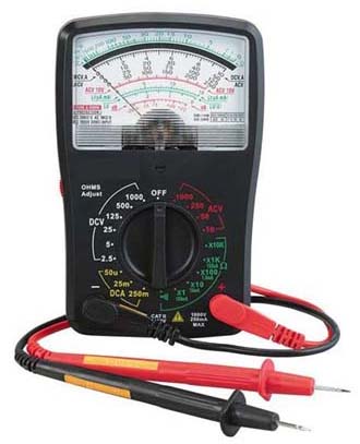
We assume the trouble has been localized to one stage or section. Remember that the receiver was probably working fine until the trouble happened. Therefore, check for simple problems first. Substitute a new tube and other plug-in components that can be replaced easily. Check for good connections at the pins of a module board or an interconnecting cable. Power circuits often have a fuse, which should be tested. Then voltage and resistance measurements can be made, using a multimeter. Normal dc voltages, measured to chassis ground, are on the manufacturer’s schematic diagram. In the signal circuits, the dc voltages are given for no ac signal input in order to eliminate the effects of AGC bias.
Dc Voltage Tests
Always check the dc supply voltages. Then measure the electrode voltages at the pins for tubes, transistors, and IC units. Normal cathode bias voltage on a tube generally means that the plate and screen-grid currents are correct. Similarly, normal emitter bias or source bias on a transistor amplifier indicates normal operation. Although the stage is usually amplifying ac signal, this function cannot be accomplished without the dc operating voltages. A dc voltage that is too high indicates an open circuit. Look for an open resistor or coil. Also, the tube or transistor may be off, creating an open circuit. A dc voltage that is too low indicates a short circuit. Look for a shorted capacitor. Also, the tube or transistor may be conducting too much current because of incorrect bias.
Resistance Tests
With the power off, resistors can be checked for an open, which reads infinity on the ohmmeter. An open coil winding or open fuse also has infinite resistance. Check capacitors for a short circuit, which reads zero on the ohmmeter. In a circuit that has B+ voltage, a shorted bypass or coupling capacitor changes the dc voltage distribution. However, an open capacitor does not affect the dc voltages. For resistance checks in transistor circuits, be sure that the ohmmeter does not give a false indication by biasing a junction on. You can open any parallel paths or use reverse polarity for the ohmmeter leads.
Resistors generally do not short but can become open because of age or excessive current. When an open resistor has a bypass capacitor, look for a short in the capacitor. This allows too much current in the resistor, burning it open. A resistor also can be partially open, with too high a resistance. Metal-film resistors often open where the leads connect to the film.
Effect Of An Open Circuit
Not only does an open circuit have infinite resistance, but its effect can be checked with a dc voltmeter. The voltage is too high at one side of an open circuit and zero at the other side. This voltage check can be used to test a resistor, coil, or fuse for an open.
Ac Voltage Tests
An oscilloscope is used for checking ac video signal and deflection volt-ages. Normal wave shapes with peak-to-peak amplitudes are shown in the manufacturer’s service notes. In the color circuits, the wave-forms are shown with signal from a color-bar generator.
Open Capacitor
This possibility can be checked by temporarily bridging the suspected capacitor with a good capacitor in parallel. Capacitor substitution boxes for this purpose are available with a wide range of capacitance values. With an ohmmeter, an open capacitor does not show charging action.
Tube-Socket Adaptor
This unit is an extension about 2 in. high. You plug the adaptor into the tube socket and the tube into the adaptor. Each pin on the adaptor has a tab for connecting the meter or oscilloscope. This way you can make connections to the tube pins from the top of the chassis.
Replacing Components
Keep the same positions for connecting leads and ground returns. This lead dress is often critical for high frequencies because of feedback and with high voltages to prevent corona and arcing. When replacing a resistor, a higher wattage rating than the original can be used. Also, a higher dc voltage rating is permissible for capacitors, except for electrolytic capacitors, which need the specified forming voltage. Do not replace mica or ceramic capacitors with tubular capacitors, because their inductance can affect the coupling or bypassing for high frequencies.
On printed-wiring boards, an individual capacitor or resistor usually can be removed easily by clipping the leads close to the component. Then the new unit is just soldered to the old leads without disturbing the eyelet connections on the board. However, desoldering tools are available to suck out the solder at the eyelet. Just be careful not to apply excessive heat to the printed wiring.


