GALVANOMETERS
MOVING COIL GALVANOMETERS OR STEADY STATE GALVANOMETER
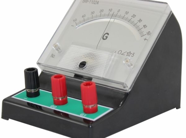
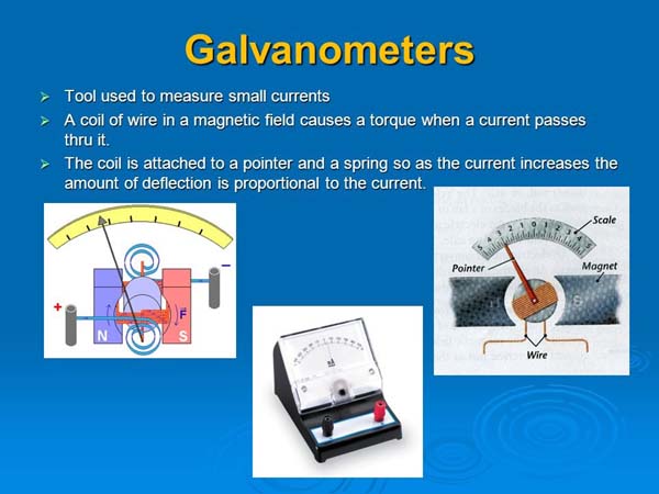
Instruments which are used to measure very small currents and voltages are designated as galvanometers. They are specially used to determine the absence of current in the detector branch of potentiometer and measuring bridges. Hence they generally have no scales graduated for current or voltage values.
HISTORY OF MOVING COIL GALVANOMETERS
In 1850 a Frechman De La Rive made a “floating magnet-. In reality it was the forerunner of the moving coil meter, although facts do not show that any attempt was made to employ the device for the measurement of current. Following De La Rive’s experiment, Varley (1956), an Englishman made a moving-coil, meter which he suggested to act as a relay. After Varley came D’Arsonral with his moving coil mirror type of galvanometer. It consisted of a coil, a permanent magnet, a mirror and a thin flat phosphor bronz ribbon used to suspend coil between poles of magnet. After this came Weston moving-coil meter in 1888. It is same as is going to be used today except for improvements in the quality of the components as a natural consequence of research.
Principle:
Basic principle behind the operation of galvanometer is the well known electrical law which states that: “A coil carrying current and located in a magnetic field will tend to so orient itself that its magnetic lines of force will be parallel to those of the magnetic field.” This means that the coil will try to shift its position in such a manner as to embrace the greatest number of lines of force. From the practical point of view it means that the coil in the moving coil galvanometer will turn as a result of the interaction between the permanent magnet field and the field created by the current flowing through the coil.
Construction:
A practical D’Arsonval galvanometer consists of the following parts:
(i) Permanent magnet. (ii) Coil with iron core. (iii) Mirror attached with Ribbon to reflect the light (iv) Phosphore-bronze strip or ribbon (v) Source of light (vi) Scale for reading(Vii) Spring
Working:
When current is passed through t h.: toil C, it will produce a magnetic field which will interact with the magnetic field of the permanent magnet. As a result, coil is deflected and light falling on the mirror from source of light will also change its position. This change in position is shown on the scale. In this way current is detected from the movement of spot of light on the scale.
Damping of moving coil galvanometer:
Reason: When a galvanometer coil is deflected through an angle 0, an amount of energy equal to S f 70cle is stored in the system in the fort, of mechanical potential energy and resides in the suspension. When current through the galvanometer is cut off, the coil will move towards its equilibrium position. If no damping is present, it will not reach the equilibrium position and start oscillating
Damping methods: (For moving coil meters)
Commonly a single closed loop of wire is added to the moving coil. When the coil moves in the magnetic field, a voltage E is generated in this loop and energy is dissipated at the rate of E2/R Joules/Sec. By making the loop of the proper resistance R, it is possible to have the coil return to its.zero position in a minimum time without oscillating. The galvanometer would then be said to be critically damped. An alternate method for producing critical damping can also be used. This is done by shunting the galvanometer coil with a certain resistance, its external critical damping resistance. When the coil starts swinging, it acts as a generator and dissipates energy in the closed circuit consisting of the coil in series with the external critical damping resistance. But this will decrease sensitivity.

