WESTON FREQUENCY METER

Principle Working of this instrument depends upon the current drawn by two parallel circuits, when frequency changes. One circuit is inductive and the other is non-inductive. Inductive circuit draws more current at lower frequency due to low impedance and hence gives more deflection. Reverse is the situation at higher frequency.
Construction:
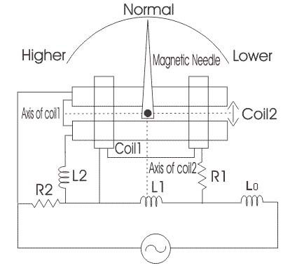
Two coils A and B are so fixed that their magnetic axes arc perpendicular to each other. At their centers is provided a long thin soft iron needle. The spindle bearing of the needle is also provided a pointer and damping vanes, but there is no controlling device. It is obvious that various circuit elements constitute a Wheatstone bridge which is balanced at the supply frequency. Coil A has a resistance RA in series with it and a reactance Lain parallel. Similarly, RB is in series with coil B and LB is in parallel. Series inductance L helps to supress higher harmonics in the current waveform and hence tends to minimize the waveform errors in the indications of the instrument.
Working:
When the instrument is connected across a supply, current passes through the coils A and B and produces opposite torques. When supply frequency is higher, the current through coil A is more whereas that through coil B is less due to the increase in the reactance offered by LB. Hence, magnetic field of coil A is stronger than that of coil B. As a result of this, magnetic nccdle lies more nearly parallel to the magnetic axis of A than to that of coil B. Reverse is the case for lower frequency.
Advantage:
This Instrument can be designed to cover a broad or narrow range of frequencies determined by the parameters of the circuit.