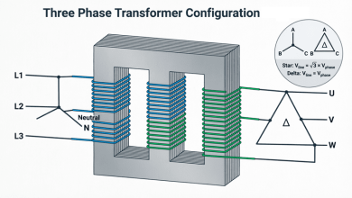
Multiple Winding Transformers
Multiple Winding Transformers: Complete Guide to Multi-Winding & Tertiary Designs
While basic transformers have one primary and one secondary winding, many practical applications require transformers with multiple windings on either the primary, secondary, or both sides. These multiple winding transformers provide flexibility in voltage selection, enable complex power distribution schemes, and serve specialized functions in electrical systems.
Multiple winding transformers are essential for:
- Dual voltage operation: Serving both 120V and 240V loads
- Multiple voltage outputs: Supplying different voltage levels from one transformer
- Harmonic mitigation: Using tertiary or zigzag windings
- Phase shifting: Creating phase displacement for special applications
- Load balancing: Distributing loads across multiple windings
- Specialized applications: Welding, furnace, and rectifier transformers
Understanding multiple winding transformer configurations is crucial for electrical engineers working with power distribution, industrial systems, and specialized equipment. This comprehensive guide will explore dual voltage transformers, multi-winding configurations, tertiary windings, connection methods, and practical applications.
What is a multiple winding transformer?
A multiple winding transformer has more than one winding on the primary, secondary, or both sides. Common configurations include dual-voltage primaries (120/240V), multiple secondaries (providing different voltages), and tertiary windings (for harmonic suppression or auxiliary power). These transformers offer flexibility in voltage selection and specialized functionality.
Dual Voltage Transformers
Dual voltage transformers are the most common type of multiple winding transformer, allowing operation at two different voltage levels.
Primary Winding Configurations
Series-Parallel Primary Windings:
The primary winding is divided into two equal sections that can be connected in series or parallel:
Series Connection (High Voltage):
- Two winding sections connected end-to-end
- Total turns = N₁ + N₂
- Voltage rating = V₁ + V₂
- Example: Two 120V windings in series = 240V operation
- Current rating = rated current of one section
Parallel Connection (Low Voltage):
- Two winding sections connected in parallel
- Total turns = N (same as one section)
- Voltage rating = V (same as one section)
- Example: Two 120V windings in parallel = 120V operation
- Current rating = 2 × rated current of one section
Terminal Markings:
Standard terminal identification (per NEMA/ANSI):
- H1, H2: First winding section
- H3, H4: Second winding section
Series Connection (240V):
- Connect H2 to H3 (jumper)
- Apply power to H1 and H4
- Voltage: 240V
Parallel Connection (120V):
- Connect H1 to H3 (jumper)
- Connect H2 to H4 (jumper)
- Apply power to H1/H3 and H2/H4
- Voltage: 120V
Secondary Winding Configurations
Similar to primaries, secondary windings can also be configured for dual voltage operation:
Example: 120/240V Secondary
Two 120V secondary windings (X1-X2 and X3-X4):
Series Connection (240V):
- Connect X2 to X3
- Output across X1 and X4
- Voltage: 240V
- Current: Rated current
Parallel Connection (120V):
- Connect X1 to X3
- Connect X2 to X4
- Output across paralleled terminals
- Voltage: 120V
- Current: 2 × rated current
Center-Tapped Configuration:
A special case where the connection point becomes a neutral:
- Series connection with center tap brought out
- Provides: 240V across ends, 120V from either end to center
- Common in residential service transformers
- Neutral carries unbalanced current
How do you connect a dual voltage transformer?
For high voltage operation, connect the two winding sections in series (add voltages). For low voltage operation, connect them in parallel (same voltage, double current). Always verify terminal markings and follow manufacturer connection diagrams to prevent damage.
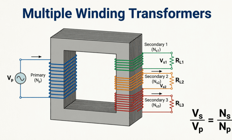
Multi-Winding Transformers (Multiple Secondaries)
Transformers with multiple independent secondary windings provide different voltage levels from a single primary, serving diverse load requirements.
Basic Configurations
Two Secondary Windings:
Common configuration providing two different voltages:
Example:
- Primary: 480V
- Secondary 1: 240V (for motors)
- Secondary 2: 120V (for controls/lighting)
Advantages:
- Single transformer replaces multiple units
- Space and cost savings
- Simplified installation
- Common magnetic core
Considerations:
- Total kVA = Sum of all secondary kVA ratings
- Each winding must be sized for its specific load
- Load imbalance affects regulation
- Fault in one winding can affect others
Three or More Secondaries:
Complex transformers serving multiple voltage requirements:
Example – Industrial Control Transformer:
- Primary: 480V
- Secondary 1: 120V (control circuits)
- Secondary 2: 24V (relays, sensors)
- Secondary 3: 12V (electronics, indicators)
Applications:
- Machine tools
- Process control systems
- Testing equipment
- Power supplies
Power Rating and Load Distribution
Total Transformer Rating:
The transformer kVA rating must accommodate all secondary loads:
$S_{total} = S_1 + S_2 + S_3 + … + S_n$
Where:
- $S_{total}$ = Total transformer kVA rating
- $S_1, S_2, …$ = Individual secondary kVA loads
Example:
- Secondary 1: 10 kVA
- Secondary 2: 5 kVA
- Secondary 3: 2 kVA
- Total: 17 kVA minimum (use 20-25 kVA transformer for margin)
Load Sharing:
Each secondary winding operates independently but shares the common magnetic core:
Primary Current:
$I_p = \frac{S_1 + S_2 + S_3}{V_p}$
Where the sum includes all secondary loads referred to the primary.
Voltage Regulation:
Loading on one secondary affects voltage on others due to:
- Common leakage reactance
- Mutual coupling
- Core saturation effects
Design Consideration: Size windings with adequate regulation margins.
Isolation Between Windings
Electrical Isolation:
Multiple secondaries provide isolated voltage sources:
Advantages:
- Prevents ground loops
- Isolates sensitive equipment
- Improves safety
- Reduces noise coupling
Insulation Requirements:
- Between windings: Full voltage insulation
- Winding to core: Ground insulation
- Between secondary windings: Based on voltage difference
Creepage and Clearance:
- Adequate spacing between terminals
- Insulation barriers between windings
- Compliance with safety standards (UL, IEC)
Tertiary Windings
Tertiary windings are additional windings beyond the primary and secondary, serving specialized functions in three-phase transformers.
Purposes of Tertiary Windings
1. Harmonic Suppression (Most Common):
Problem:
- Three-phase transformers with delta-wye connections
- Third harmonic currents cannot flow in wye without neutral
- Causes voltage distortion and overheating
Solution:
- Delta-connected tertiary winding
- Provides path for third harmonic (triplen) currents
- Circulates within delta, doesn’t appear in lines
- Sinusoidal voltage waveform maintained
How It Works:
- Third harmonic voltages are in-phase in all three phases
- Delta connection allows circulating current
- Harmonic MMF cancels fundamental MMF
- Reduces harmonic distortion
2. Stabilization:
Unbalanced Load Conditions:
- Wye-wye transformers without delta tertiary
- Zero-sequence currents have no path
- Neutral shift under unbalanced loads
- Voltage imbalance
Tertiary Provides:
- Path for zero-sequence currents
- Stabilizes neutral point
- Improves voltage balance
- Limits fault currents
3. Auxiliary Power Supply:
Substation Applications:
- Main transformer: High voltage to distribution voltage
- Tertiary winding: Low voltage for station service
- Powers: Control systems, cooling fans, lighting, battery chargers
- Eliminates separate service transformer
Typical Ratings:
- Main secondary: 13.8 kV or 34.5 kV
- Tertiary: 480V or 240V
- Tertiary kVA: 50-500 kVA (depending on station needs)
4. Reactive Power Compensation:
Shunt Reactor Connection:
- Tertiary winding connects shunt reactors
- Controls system voltage
- Absorbs reactive power
- Prevents overvoltage during light load
Capacitor Bank Connection:
- Connects power factor correction capacitors
- Supplies reactive power
- Improves system power factor
- Reduces losses
Tertiary Winding Configurations
Delta Connection (Most Common):
Advantages:
- Provides path for triplen harmonics
- Circulating currents stay within delta
- No external connection required (often)
- Simple construction
Rating:
- Typically 25-40% of main transformer rating
- Sized for harmonic current circulation
- Must handle fault currents
Wye Connection:
Applications:
- When tertiary supplies auxiliary loads
- Provides neutral for grounding
- Can supply single-phase loads
Considerations:
- Must provide harmonic path (may need zigzag)
- Neutral grounding required
- More complex protection
Zigzag Connection:
Special Configuration:
- Provides grounding without delta
- Low zero-sequence impedance
- Harmonic suppression
- Ground fault current path
Applications:
- Grounding transformers
- Arc suppression
- Harmonic mitigation
Sizing Tertiary Windings
For Harmonic Suppression:
- Minimum: 25% of main rating
- Typical: 33-40% of main rating
- Based on harmonic current magnitude
- Must not overheat from circulating currents
For Auxiliary Power:
- Based on connected load
- Diversity factor applied
- Future expansion considered
- Typical: 50-500 kVA
For Stabilization:
- Based on unbalanced load requirements
- Fault current considerations
- System grounding requirements
- Engineering analysis required
Example Calculation:
Given:
- Main transformer: 10 MVA
- Purpose: Harmonic suppression
- Harmonic content: 5% third harmonic
Tertiary Rating:
$S_{tertiary} = 0.33 \times S_{main}$
$S_{tertiary} = 0.33 \times 10,000 = 3,300 \text{ kVA}$
Use: 3.3 MVA or 4 MVA tertiary winding
What is the purpose of a tertiary winding?
Tertiary windings serve multiple purposes: (1) Suppress third harmonics by providing a delta path for circulating currents, (2) Stabilize neutral point under unbalanced loads, (3) Supply auxiliary power for substation equipment, and (4) Connect reactive power compensation equipment. Most common in large three-phase power transformers.
Autotransformers
Note: Autotransformers are covered in detail in Article 5. Brief overview here:
Definition:
Transformer with single winding serving as both primary and secondary, with taps providing different voltage ratios.
Advantages:
- Smaller size and cost (less copper)
- Higher efficiency (lower losses)
- Better voltage regulation
Disadvantages:
- No electrical isolation
- Higher fault currents
- Limited voltage ratio
Applications:
- Voltage regulation
- Motor starting
- Interconnecting systems
Special Multiple Winding Configurations
Zigzag Transformers
Configuration:
- Six windings on three-phase core
- Interconnected in zigzag pattern
- No secondary output (grounding only)
Applications:
- Ground fault current path
- Harmonic suppression
- Neutral grounding
- Arc suppression coils
Advantages:
- Low zero-sequence impedance
- High positive/negative sequence impedance
- Compact size
- Effective grounding
Split Winding Transformers
Configuration:
- Secondary winding split into two or more sections
- Electrically isolated from each other
- Common primary
Applications:
- Dual power supplies
- Redundant systems
- Load separation
- Noise isolation
Example:
- Primary: 480V
- Secondary A: 120V (critical loads)
- Secondary B: 120V (non-critical loads)
- Isolated to prevent fault propagation
Scott-T Connection
Purpose:
- Convert three-phase to two-phase
- Or two-phase to three-phase
Configuration:
- Two single-phase transformers
- Main transformer (86.6% tap)
- Teaser transformer (50% tap)
Applications:
- Legacy two-phase systems
- Special industrial applications
- Railway electrification (historical)
Practical Applications
1. Residential Service Transformers
Configuration:
- Primary: 7200V or 13.8kV (distribution voltage)
- Secondary: 120/240V split-phase
- Center-tapped secondary
Connections:
- Series secondary with center tap
- Provides: 240V across ends, 120V to center
- Center tap grounded (neutral)
Loads:
- 240V: Water heater, A/C, dryer, range
- 120V: Lighting, outlets, appliances
- Neutral carries unbalanced current
2. Industrial Control Transformers
Configuration:
- Primary: 480V or 600V
- Secondary 1: 120V (control circuits)
- Secondary 2: 24V (relays, PLCs)
- Secondary 3: 12V or 5V (electronics)
Features:
- Multiple isolated secondaries
- Fuse protection on each secondary
- Compact design
- High reliability
3. Rectifier Transformers
Configuration:
- Primary: Three-phase
- Multiple secondaries with phase shift
- Feeds rectifier bridges
Purpose:
- DC power supply (electroplating, aluminum smelting)
- Reduce harmonic distortion
- Increase pulse number
Example – 12-Pulse Rectifier:
- Primary: Delta or Wye
- Secondary 1: Wye (0° shift)
- Secondary 2: Delta (30° shift)
- Two 6-pulse bridges
- Combined output: 12-pulse DC
- Reduced 5th and 7th harmonics
4. Welding Transformers
Configuration:
- Primary: Multiple taps for voltage adjustment
- Secondary: Low voltage, high current
- Movable core or winding for current control
Characteristics:
- High leakage reactance (current limiting)
- Low secondary voltage (20-80V)
- High secondary current (100-1000A)
- Adjustable output
5. Furnace Transformers
Configuration:
- Primary: High voltage
- Secondary: Very low voltage, very high current
- Multiple taps for voltage control
- Often water-cooled
Applications:
- Arc furnaces (steel making)
- Resistance furnaces
- Induction heating
Characteristics:
- Secondary voltage: 100-1000V
- Secondary current: 10,000-100,000A
- Robust construction
- High short-circuit strength
Connection and Installation Considerations
Terminal Identification
Standard Markings (NEMA/ANSI):
Primary (High Voltage):
- H1, H2, H3, H4 (single-phase)
- H1, H2, H3 (three-phase)
Secondary (Low Voltage):
- X1, X2, X3, X4 (single-phase)
- X1, X2, X3 (three-phase)
Tertiary:
- Y1, Y2, Y3 (if applicable)
Polarity:
- Dot convention or additive/subtractive
- Critical for parallel operation
- Must verify before connection
Parallel Operation
Multiple winding transformers in parallel:
Requirements:
- Same voltage ratios
- Same polarity
- Same phase sequence (three-phase)
- Same percentage impedance
- Same X/R ratio
Challenges:
- Complex winding configurations
- Circulating currents between windings
- Load sharing imbalances
- Harmonic interactions
Solution:
- Careful design and matching
- Impedance measurements
- Load testing
- Professional engineering
Protection Requirements
Overcurrent Protection:
- Primary side: Based on total kVA
- Each secondary: Individual protection
- Coordination between protections
- Time-current curves
Ground Fault Protection:
- Especially important for multi-winding
- Detect faults in any winding
- Prevent damage propagation
- Ground fault relays
Overload Protection:
- Thermal protection
- Temperature monitoring
- Load monitoring
- Alarm and trip functions
Differential Protection:
- For large multi-winding transformers
- Compare currents in all windings
- Detect internal faults
- Fast operation
Practical Examples and Calculations
Example 1: Dual Voltage Transformer Connection
Problem: A 5 kVA transformer has dual primary windings rated 120V each (H1-H2 and H3-H4) and dual secondary windings rated 12V each (X1-X2 and X3-X4). Show connections for:
- 240V primary, 24V secondary
- 120V primary, 12V secondary
- 120V primary, 24V secondary
Solution:
Configuration 1: 240V Primary, 24V Secondary
- Primary: Series connection
- Connect H2 to H3 (jumper)
- Apply 240V to H1 and H4
- Secondary: Series connection
- Connect X2 to X3 (jumper)
- Output 24V from X1 and X4
- Rating: 5 kVA at 24V = 208A secondary current
Configuration 2: 120V Primary, 12V Secondary
- Primary: Parallel connection
- Connect H1 to H3 (jumper)
- Connect H2 to H4 (jumper)
- Apply 120V to H1/H3 and H2/H4
- Secondary: Parallel connection
- Connect X1 to X3 (jumper)
- Connect X2 to X4 (jumper)
- Output 12V from paralleled terminals
- Rating: 5 kVA at 12V = 417A secondary current
Configuration 3: 120V Primary, 24V Secondary
- Primary: Parallel connection (as above)
- Secondary: Series connection
- Connect X2 to X3 (jumper)
- Output 24V from X1 and X4
- Rating: 5 kVA at 24V = 208A secondary current
Verification:
- Configuration 1: 240V × 20.8A = 5 kVA ✓
- Configuration 2: 120V × 41.7A = 5 kVA ✓
- Configuration 3: 120V × 41.7A = 5 kVA primary, 24V × 208A = 5 kVA secondary ✓
Example 2: Multi-Winding Transformer Loading
Problem: A transformer has three secondary windings:
- Winding 1: 120V, 50A rating
- Winding 2: 24V, 100A rating
- Winding 3: 12V, 50A rating
The primary is rated 480V. Calculate:
- Total transformer kVA rating
- Primary current at full load
- If winding 1 supplies 4 kVA, winding 2 supplies 1.5 kVA, and winding 3 supplies 0.3 kVA, calculate primary current
Solution:
Part 1: Total kVA Rating
Winding 1: $S_1 = 120V \times 50A = 6,000 \text{ VA} = 6 \text{ kVA}$
Winding 2: $S_2 = 24V \times 100A = 2,400 \text{ VA} = 2.4 \text{ kVA}$
Winding 3: $S_3 = 12V \times 50A = 600 \text{ VA} = 0.6 \text{ kVA}$
Total: $S_{total} = 6 + 2.4 + 0.6 = 9 \text{ kVA}$
Use 10 kVA transformer for margin.
Part 2: Primary Current at Full Load
$I_p = \frac{S_{total}}{V_p} = \frac{9,000}{480} = 18.75 \text{ A}$
Part 3: Primary Current at Actual Load
Actual loads:
- Winding 1: 4 kVA
- Winding 2: 1.5 kVA
- Winding 3: 0.3 kVA
- Total: 5.8 kVA
$I_p = \frac{5,800}{480} = 12.08 \text{ A}$
Loading percentage: $\frac{5.8}{9} \times 100\% = 64.4\%$
Result: Transformer is operating at 64.4% load with 12.08A primary current.
Example 3: Tertiary Winding Sizing
Problem: A 15 MVA, 138/13.8 kV transformer requires a tertiary winding for harmonic suppression. The third harmonic content is estimated at 4% of fundamental. Calculate the required tertiary rating and verify it can handle the harmonic current.
Solution:
Given:
- Main rating: 15 MVA
- Harmonic content: 4% third harmonic
- Purpose: Harmonic suppression
Tertiary Rating (Rule of Thumb):
$S_{tertiary} = 0.33 \times S_{main}$
$S_{tertiary} = 0.33 \times 15 = 4.95 \text{ MVA}$
Use: 5 MVA tertiary winding
Harmonic Current Calculation:
Fundamental current (secondary side):
$I_{fund} = \frac{S}{\sqrt{3} \times V} = \frac{15,000}{\sqrt{3} \times 13.8} = \frac{15,000}{23.9} = 627.6 \text{ A}$
Third harmonic current:
$I_3 = 0.04 \times I_{fund} = 0.04 \times 627.6 = 25.1 \text{ A}$
Tertiary Current (Delta Connection):
For delta-connected tertiary at 13.8 kV:
$I_{tertiary} = \frac{S_{tertiary}}{\sqrt{3} \times V} = \frac{5,000}{\sqrt{3} \times 13.8} = \frac{5,000}{23.9} = 209.2 \text{ A}$
Verification:
Tertiary rating (209A) >> Harmonic current (25A) ✓
The 5 MVA tertiary can easily handle the 4% third harmonic current with significant margin.
Result: Specify 5 MVA tertiary winding, delta-connected.
Multiple winding transformers provide essential flexibility and functionality in electrical power systems. From simple dual-voltage configurations to complex multi-winding arrangements with tertiary windings, these transformers serve diverse applications across residential, commercial, and industrial sectors.
Key takeaways from this guide:
- Dual Voltage Transformers:
- Series connection for high voltage operation
- Parallel connection for low voltage, high current
- Common in distribution and control transformers
- Proper terminal identification critical
- Multi-Winding Transformers:
- Multiple independent secondary windings
- Provide different voltage levels from one primary
- Total kVA = sum of all secondary kVA ratings
- Electrical isolation between windings
- Tertiary Windings:
- Suppress third harmonics (delta connection)
- Stabilize neutral under unbalanced loads
- Supply auxiliary power in substations
- Typically 25-40% of main transformer rating
- Special Configurations:
- Zigzag for grounding
- Split windings for redundancy
- Scott-T for phase conversion
- Rectifier transformers for DC power
- Applications:
- Residential service (120/240V split-phase)
- Industrial controls (multiple low voltages)
- Power rectification (phase-shifting secondaries)
- Welding and furnace (high current, low voltage)
- Design Considerations:
- Proper sizing for all windings
- Voltage regulation under varying loads
- Protection coordination
- Thermal management
- Insulation requirements
- Installation:
- Correct terminal connections
- Polarity verification
- Grounding requirements
- Protection devices
- Load balancing
Mastering multiple winding transformer concepts enables engineers to design efficient power distribution systems, select appropriate transformers for complex applications, and troubleshoot multi-winding installations. Whether working with simple dual-voltage transformers or complex multi-winding power transformers, understanding these configurations is essential for modern electrical engineering practice.