Transformer Voltage Regulation
Transformer Voltage Regulation: Complete Guide to Calculation and Improvement
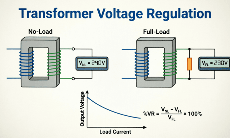
The transformer would deliver the exact same secondary voltage regardless of how much load is connected to it. However, in the real world, as soon as you connect a load to a transformer, the secondary voltage drops. This phenomenon is known as voltage regulation.
Transformer voltage regulation is a critical performance parameter that measures the change in secondary terminal voltage from no-load to full-load conditions, expressed as a percentage of the full-load voltage. It directly impacts the quality of power delivered to end-users. Poor voltage regulation can cause lights to dim, motors to overheat, and sensitive electronic equipment to malfunction.
Understanding voltage regulation is essential for electrical engineers designing power distribution systems, selecting appropriate transformers, and implementing voltage correction strategies. This comprehensive guide will explore the causes of voltage regulation, the mathematical formulas used to calculate it, the profound effect of load power factor, and practical methods to improve it.
What is transformer voltage regulation?
Transformer voltage regulation is the percentage change in secondary voltage from no-load to full-load. It is caused by the internal resistance and leakage reactance of the transformer windings. Good voltage regulation means the voltage remains stable as the load changes, while poor regulation results in significant voltage drops under heavy loads.
Definition and Mathematical Formulas
The Exact Formula
Voltage regulation (VR) is defined as the difference between the no-load secondary voltage ($V_{NL}$) and the full-load secondary voltage ($V_{FL}$), expressed as a percentage of the full-load voltage.
$\% \text{VR} = \frac{V_{NL} – V_{FL}}{V_{FL}} \times 100\%$
Where:
- $V_{NL}$ = Secondary terminal voltage at no-load (with rated primary voltage applied)
- $V_{FL}$ = Secondary terminal voltage at full-load (rated load)
Note: Some standards (like IEC) use $V_{NL}$ in the denominator. The IEEE standard typically uses $V_{FL}$ as the base. Always verify which standard your local codes require, though the IEEE method is most common in North American engineering practice.
Why Does Voltage Drop Occur?
When a transformer is at no-load, the secondary current is zero. Therefore, there is no voltage drop across the internal winding resistance or leakage reactance, and the secondary terminal voltage equals the induced electromotive force (EMF).
When a load is applied, current flows through the secondary winding. This current encounters two internal obstacles:
- Winding Resistance ($R$): Causes a voltage drop in phase with the current ($I \times R$).
- Leakage Reactance ($X$): Caused by magnetic flux that does not link both windings. It causes a voltage drop that is 90° out of phase with the current ($I \times X$).
The vector sum of the induced EMF and these internal voltage drops results in a lower terminal voltage at the load.
What causes voltage drop in a transformer?
Voltage drop in a transformer is caused by its internal winding resistance and leakage reactance. When load current flows, it creates internal voltage drops ($I \times R$ and $I \times X$), reducing the voltage available at the secondary terminals compared to the no-load condition.
The Effect of Load Power Factor on Regulation
The load’s power factor (PF) has a dramatic impact on transformer voltage regulation. Because the internal voltage drops are vector quantities, their effect on the terminal voltage depends entirely on the phase angle between the load current and the secondary voltage.
1. Lagging Power Factor (Inductive Load)
- Behavior: Current lags the voltage.
- Effect: The resistive drop ($I \times R$) and reactive drop ($I \times X$) both act to reduce the terminal voltage.
- Result: Positive voltage regulation (voltage drops significantly). This is the worst-case scenario for regulation and is typical of industrial motor loads.
2. Unity Power Factor (Resistive Load)
- Behavior: Current is in phase with the voltage.
- Effect: The resistive drop directly reduces the voltage, while the reactive drop has a minimal perpendicular effect.
- Result: Moderate positive voltage regulation. Better than lagging PF, but still a noticeable drop.
3. Leading Power Factor (Capacitive Load)
- Behavior: Current leads the voltage.
- Effect: The reactive voltage drop ($I \times X$) actually adds to the terminal voltage, partially or fully canceling the resistive drop.
- Result: Zero or Negative voltage regulation. The full-load voltage can actually be higher than the no-load voltage. This is known as the Ferranti Effect and is common in lightly loaded long transmission lines or systems with heavy capacitor banks.
The Approximate Voltage Regulation Formula
Calculating the exact voltage regulation requires complex phasor (vector) math. In practical engineering, an approximate formula is universally used because it is highly accurate for normal operating conditions and much simpler to calculate.
$\% \text{VR} \approx (\%R \times \cos\theta) \pm (\%X \times \sin\theta)$
Where:
- $\%R$ = Percentage resistance of the transformer ($\frac{I_{FL} \times R_{eq}}{V_{FL}} \times 100\%$)
- $\%X$ = Percentage leakage reactance ($\frac{I_{FL} \times X_{eq}}{V_{FL}} \times 100\%$)
- $\cos\theta$ = Load power factor
- $\sin\theta$ = Reactive factor ($\sqrt{1 – \cos^2\theta}$)
The Sign Convention:
- Use (+) for lagging power factor (inductive loads).
- Use (-) for leading power factor (capacitive loads).
Percentage Impedance ($\%Z$)
Transformers are often specified by their percentage impedance ($\%Z$), which is the voltage drop at full load expressed as a percentage of rated voltage.
$\%Z = \sqrt{(\%R)^2 + (\%X)^2}$
Typical values:
- Small distribution transformers: $\%Z \approx 2\%$ to $4\%$
- Large power transformers: $\%Z \approx 5\%$ to $10\%$
How does power factor affect voltage regulation?
Lagging power factor (inductive loads) causes the worst voltage drop (positive regulation). Unity power factor causes a moderate drop. Leading power factor (capacitive loads) can cause the voltage to rise, resulting in zero or negative regulation (Ferranti effect).
Transformer Equivalent Circuit for Regulation
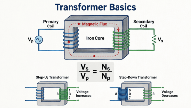
To accurately model voltage regulation, engineers use the approximate equivalent circuit of a transformer, referred to either the primary or secondary side.
When referred to the secondary side, the circuit consists of:
- Ideal Transformer: (Often omitted in secondary-referred calculations, replaced by the induced voltage $E_s$).
- Equivalent Resistance ($R_{eq}$): The sum of primary and secondary resistances, scaled to the secondary side.
- Equivalent Leakage Reactance ($X_{eq}$): The sum of primary and secondary leakage reactances, scaled to the secondary side.
The voltage equation becomes:
$\mathbf{V_{NL}} = \mathbf{V_{FL}} + \mathbf{I_{FL}}(R_{eq} + jX_{eq})$
Because $R_{eq}$ and $X_{eq}$ are in series with the load, any increase in load current ($I_{FL}$) directly increases the internal voltage drop, lowering the terminal voltage $V_{FL}$.
Practical Examples and Calculations
Example 1: Basic Voltage Regulation Calculation
Problem: A single-phase transformer has a no-load secondary voltage of 240V. When supplying its rated full load, the secondary voltage drops to 228V. Calculate the percentage voltage regulation.
Solution:
Given:
- $V_{NL} = 240\text{V}$
- $V_{FL} = 228\text{V}$
Formula:
$\% \text{VR} = \frac{V_{NL} – V_{FL}}{V_{FL}} \times 100\%$
Calculation:
$\% \text{VR} = \frac{240 – 228}{228} \times 100\%$
$\% \text{VR} = \frac{12}{228} \times 100\%$
$\% \text{VR} = 0.0526 \times 100\% = 5.26\%$
Result: The transformer has a voltage regulation of 5.26%.
Example 2: Approximate Formula with Different Power Factors
Problem: A 50 kVA, 2400/240V transformer has a percentage resistance of $\%R = 1.2\%$ and a percentage reactance of $\%X = 4.5\%$. Calculate the voltage regulation at full load for:
- 0.8 lagging power factor
- Unity (1.0) power factor
- 0.8 leading power factor
Solution:
Given:
- $\%R = 1.2\%$
- $\%X = 4.5\%$
1. At 0.8 Lagging PF:
- $\cos\theta = 0.8$
- $\sin\theta = \sqrt{1 – 0.8^2} = 0.6$
- Use the (+) sign for lagging.
$\% \text{VR} \approx (1.2 \times 0.8) + (4.5 \times 0.6)$
$\% \text{VR} \approx 0.96 + 2.70 = \mathbf{3.66\%}$
2. At Unity (1.0) PF:
- $\cos\theta = 1.0$
- $\sin\theta = 0$
$\% \text{VR} \approx (1.2 \times 1.0) + (4.5 \times 0)$
$\% \text{VR} \approx \mathbf{1.2\%}$
3. At 0.8 Leading PF:
- $\cos\theta = 0.8$
- $\sin\theta = 0.6$
- Use the (-) sign for leading.
$\% \text{VR} \approx (1.2 \times 0.8) – (4.5 \times 0.6)$
$\% \text{VR} \approx 0.96 – 2.70 = \mathbf{-1.74\%}$
Result:
- Lagging PF causes a 3.66% voltage drop.
- Unity PF causes a 1.2% voltage drop.
- Leading PF causes a 1.74% voltage rise (negative regulation).
Example 3: Determining Actual Load Voltage
Problem: Using the transformer from Example 2, if the no-load voltage is 240V, what is the actual full-load voltage when supplying a 0.8 lagging power factor load?
Solution:
Given:
- $V_{NL} = 240\text{V}$
- $\% \text{VR} = 3.66\%$ (from Example 2)
Formula rearrangement:
$\% \text{VR} = \frac{V_{NL} – V_{FL}}{V_{FL}} \times 100\%$
$0.0366 = \frac{240 – V_{FL}}{V_{FL}}$
$0.0366 \times V_{FL} = 240 – V_{FL}$
$1.0366 \times V_{FL} = 240$
$V_{FL} = \frac{240}{1.0366} = \mathbf{231.5\text{V}}$
Result: The actual full-load voltage is 231.5V.
Methods to Improve Voltage Regulation
Poor voltage regulation can be mitigated through several design and operational strategies:
1. Tap Changers
Transformers are equipped with taps (connection points) on the primary winding to adjust the turns ratio.
- Off-Load Tap Changers (OLTC): Require the transformer to be de-energized to change taps. Used for seasonal or permanent load changes.
- On-Load Tap Changers (OLTC): Can adjust the turns ratio while the transformer is energized and under load. Automatically maintains secondary voltage within a tight band (e.g., ±2%) despite load fluctuations. Standard on large distribution and power transformers.
2. Shunt Capacitor Banks
Adding capacitors in parallel with inductive loads supplies leading reactive power locally. This cancels out the lagging reactive power drawn by motors, improving the overall system power factor. As shown in the approximate formula, improving the power factor (moving it closer to unity) directly reduces the $\%X \sin\theta$ voltage drop term.
3. Series Capacitors
In long distribution lines, series capacitors are inserted directly into the line. They provide a negative reactance that directly cancels out the positive leakage reactance ($X_{eq}$) of the line and transformer, dramatically reducing the $I \times X$ voltage drop.
4. Automatic Voltage Regulators (AVR)
AVRs are electronic or electromechanical devices that continuously monitor the output voltage and inject a compensating voltage (via a booster transformer or solid-state electronics) to maintain a constant output level.
5. Transformer Design Improvements
Manufacturers can improve regulation by:
- Using larger conductor cross-sections to reduce $\%R$.
- Improving winding geometry (e.g., interleaved or sandwich windings) to reduce leakage flux and lower $\%X$.
- Using higher-grade core materials to reduce the magnetizing current, though this has a minor effect on full-load regulation.
Transformer voltage regulation is a fundamental metric of power quality, defining how well a transformer maintains its secondary voltage as the load varies. It is an unavoidable consequence of the physical reality that transformer windings possess internal resistance and leakage reactance.
Key takeaways from this guide:
- Definition: Voltage regulation is the percentage change in secondary voltage from no-load to full-load: $\%VR = \frac{V_{NL} – V_{FL}}{V_{FL}} \times 100\%$.
- Causes: Internal winding resistance ($R$) and leakage reactance ($X$) cause voltage drops proportional to the load current.
- Power Factor Impact:
- Lagging PF causes the highest voltage drop (positive regulation).
- Unity PF causes a moderate drop.
- Leading PF can cause a voltage rise (negative regulation).
- Approximate Formula: $\%VR \approx (\%R \cos\theta) \pm (\%X \sin\theta)$ is the standard engineering tool for quick, accurate calculations.
- Improvement Methods: On-load tap changers (OLTC), shunt capacitor banks for power factor correction, series capacitors, and automatic voltage regulators (AVR) are the primary methods used to maintain stable voltage.
Mastering voltage regulation concepts allows electrical engineers to properly size transformers, predict system performance under varying loads, and design effective voltage support systems. Whether you are designing a microgrid, troubleshooting dimming lights in a commercial building, or specifying a utility substation transformer, understanding voltage regulation is essential for ensuring reliable, high-quality electrical power delivery.