Transformer Construction
Transformer Construction: Complete Guide to Core, Windings & Design
The construction of a transformer is a critical aspect that determines its performance, efficiency, reliability, and cost. While all transformers operate on the same basic principle of electromagnetic induction, their physical construction can vary significantly depending on the application, power rating, voltage level, and frequency of operation.
Understanding transformer construction is essential for:
- Selection: Choosing the right transformer for specific applications
- Maintenance: Proper inspection and servicing procedures
- Troubleshooting: Identifying construction-related failures
- Design: Specifying transformers for custom applications
- Installation: Proper handling and mounting requirements
This comprehensive guide will explore every aspect of transformer construction, from core materials and configurations to winding arrangements, insulation systems, cooling methods, and protective devices. Whether you’re working with small signal transformers or massive power transformers, understanding construction details is fundamental to effective electrical engineering practice.
What are the main components of a transformer?
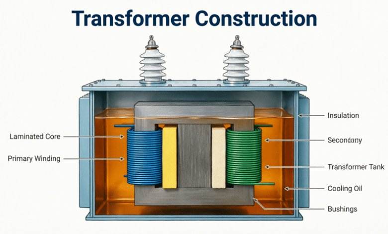
The main components are: (1) Core – laminated steel structure providing magnetic path, (2) Windings – primary and secondary coils (copper or aluminum), (3) Insulation – materials separating windings and core, (4) Tank/Enclosure – protective housing, (5) Cooling system – oil, air, or other cooling medium, and (6) Accessories – bushings, tap changers, protection devices.
Core Construction
The transformer core is the foundation of transformer construction, providing a low-reluctance path for magnetic flux. Core design significantly affects efficiency, size, weight, and cost.
Core Materials
1. Silicon Steel (Most Common)
Silicon steel (also called electrical steel) is the standard material for power and distribution transformers:
Composition:
- Iron with 3-5% silicon content
- Silicon increases electrical resistivity, reducing eddy current losses
- Improves magnetic permeability
Lamination:
- Core is built from thin laminations (0.23mm to 0.35mm thick)
- Laminations are insulated from each other (varnish or oxide coating)
- Reduces eddy current losses by restricting current paths
- Typical lamination thickness:
- 50/60 Hz: 0.35mm
- 400 Hz: 0.23mm
- Higher frequencies: Thinner laminations
Grain-Oriented Steel:
- Crystal structure aligned in rolling direction
- Superior magnetic properties in one direction
- Lower core losses (1.0-1.5 W/kg vs. 2-3 W/kg for non-oriented)
- Used in power transformers
- More expensive but more efficient
Non-Grain-Oriented Steel:
- Uniform magnetic properties in all directions
- Used in rotating machines and small transformers
- Lower cost
- Higher losses than grain-oriented
2. Amorphous Steel
Amorphous (non-crystalline) steel represents advanced core technology:
Characteristics:
- Rapidly cooled molten metal (no crystalline structure)
- Very thin ribbons (0.025mm thick)
- Core losses 70-80% lower than silicon steel
- No-load losses reduced dramatically
Advantages:
- Higher efficiency (especially at light loads)
- Lower operating temperature
- Environmentally friendly (reduced energy waste)
- Ideal for distribution transformers (24/7 operation)
Disadvantages:
- 2-3 times more expensive than silicon steel
- More brittle and difficult to cut
- Limited to certain core configurations
- Higher material cost but lower lifetime cost
Applications:
- Energy-efficient distribution transformers
- Green building projects
- Utilities with high energy conservation goals
3. Ferrite
Ferrite cores are ceramic magnetic materials:
Composition:
- Iron oxide mixed with other metals (manganese, zinc, nickel)
- Sintered at high temperatures
Characteristics:
- Very high electrical resistivity
- Virtually no eddy current losses
- Operates at high frequencies (kHz to MHz)
- Lower saturation flux density than steel
Applications:
- Switch-mode power supplies (SMPS)
- High-frequency transformers
- RF transformers
- Inductors and chokes
4. Air Core
Air core transformers have no magnetic material:
Characteristics:
- Windings supported by non-magnetic forms
- No core losses
- Very low inductance
- Linear B-H curve (no saturation)
Applications:
- Radio frequency (RF) circuits
- Very high-frequency applications (>100 kHz)
- Measurement standards
- Specialized applications requiring linearity
Core Configurations
Transformers use two primary core configurations:
1. Core-Type Construction
In core-type transformers, the windings surround the core:
Structure:
- Single magnetic circuit
- Two vertical limbs connected by top and bottom yokes
- Windings placed on both limbs
- Each limb carries half primary and half secondary
Advantages:
- Better cooling (windings exposed)
- Easier to insulate and repair
- Lower leakage reactance
- Preferred for high-voltage applications
Disadvantages:
- Longer mean length of core
- More core material required
- Larger size for same rating
Applications:
- High-voltage power transformers
- Distribution transformers
- Most common construction type
2. Shell-Type Construction
In shell-type transformers, the core surrounds the windings:
Structure:
- Double magnetic circuit
- Central limb carries both windings
- Two outer limbs provide return path
- Windings sandwiched between core sections
Advantages:
- Better mechanical support for windings
- Shorter mean length of core
- Less core material
- Better short-circuit strength
- Compact design
Disadvantages:
- More difficult to insulate
- Harder to repair
- Poorer cooling
- Higher leakage reactance
Applications:
- Low-voltage, high-current transformers
- Furnace transformers
- Welding transformers
- Small power transformers
3. Berry-Type (Distributed Core)
A variation combining features of both:
Structure:
- Multiple magnetic circuits
- Core distributed around windings
- Cylindrical arrangement
Applications:
- Very large power transformers
- Specialized applications
What is the difference between core-type and shell-type transformers?
In core-type transformers, windings surround the core limbs (better cooling, easier maintenance). In shell-type transformers, the core surrounds the windings (more compact, better mechanical strength). Core-type is preferred for high-voltage applications; shell-type for high-current applications.
Winding Construction
Transformer windings are the conductive elements that carry current and create the magnetic field. Winding design affects efficiency, voltage regulation, short-circuit strength, and cost.
Winding Materials
1. Copper
Copper is the preferred material for most transformers:
Advantages:
- Highest conductivity (second only to silver)
- Smaller cross-section for same current
- Better mechanical strength
- Easier to solder and connect
- More resistant to corrosion
Disadvantages:
- Higher cost (3-5 times aluminum)
- Heavier weight
- Subject to theft (scrap value)
Applications:
- High-efficiency transformers
- Space-constrained designs
- Critical applications
- Most distribution and power transformers
2. Aluminum
Aluminum is increasingly common, especially in distribution transformers:
Advantages:
- Lower cost
- Lighter weight (1/3 of copper)
- Good conductivity (61% of copper)
- Abundant supply
Disadvantages:
- Larger cross-section required (1.6 times copper)
- Lower mechanical strength
- More difficult to connect (oxidation, creep)
- Higher thermal expansion
- Requires special termination techniques
Applications:
- Distribution transformers
- Cost-sensitive applications
- Large power transformers (weight savings)
- Utilities with budget constraints
Winding Types
1. Concentric Windings
Most common arrangement where windings are cylindrical and concentric:
Structure:
- Low-voltage winding placed nearer to core
- High-voltage winding placed outside
- Cylindrical layers
- Insulation between layers
Advantages:
- Simple construction
- Good cooling
- Easy to insulate
- Lower leakage reactance
Variations:
- Cylindrical: For low-voltage, high-current
- Helical: For medium ratings
- Disc/Continuous: For high-voltage
- Cross-over: For small transformers
2. Sandwich (Interleaved) Windings
Windings are divided into sections and interleaved:
Structure:
- HV and LV sections alternate
- Multiple sections stacked axially
- Better coupling between windings
Advantages:
- Lower leakage reactance
- Better voltage distribution
- Reduced short-circuit forces
- Improved regulation
Disadvantages:
- More complex construction
- Higher cost
- More insulation required
Applications:
- High-current transformers
- Furnace transformers
- Welding transformers
- Special applications requiring low reactance
3. Disc Windings
Used for high-voltage applications:
Structure:
- Winding formed as flat discs
- Multiple discs stacked axially
- Radial cooling ducts between discs
- Continuous or interleaved disc arrangement
Advantages:
- Excellent insulation between turns
- Good cooling
- Handles high voltages well
- Mechanically robust
Applications:
- High-voltage power transformers (>33 kV)
- Generator step-up transformers
- Transmission transformers
Winding Insulation
Proper insulation is critical for transformer reliability:
Turn-to-Turn Insulation:
- Enamel coating on wire
- Paper wrapping
- Nomex or other synthetic materials
- Prevents short circuits between adjacent turns
Layer Insulation:
- Insulating paper or pressboard between layers
- Oil ducts for cooling
- Prevents layer-to-layer breakdown
Winding-to-Winding Insulation:
- Major insulation barrier between HV and LV
- Oil gaps and solid insulation
- Cylindrical barriers or rings
- Withstands full voltage difference
Winding-to-Core Insulation:
- Insulating cylinders
- Pressboard spacers
- Oil ducts
- Prevents ground faults
Insulation Materials:
- Kraft Paper: Traditional, oil-impregnated
- Pressboard: Dense cellulose, high mechanical strength
- Nomex: Aramid paper, high temperature (220°C)
- Mylar: Polyester film, good dielectric strength
- Epoxy: Cast resin for dry-type transformers
- Silicone Rubber: High temperature, flexible
Why is the low-voltage winding placed closer to the core?
The LV winding is placed nearer the core because it requires less insulation from the grounded core. This reduces insulation cost and size. The HV winding is placed outside where it has more space for insulation and better cooling.
Insulation Systems
Transformer insulation prevents electrical breakdown between components at different potentials and provides mechanical support.
Liquid Insulation (Oil)
Mineral Oil (Most Common):
Functions:
- Insulation: Dielectric strength ~30 kV/mm
- Cooling: Transfers heat from windings to tank
- Arc quenching: Suppresses arcs in tap changers
- Diagnostic: Oil analysis reveals transformer condition
Properties:
- Dielectric strength: 30-40 kV (new oil)
- Viscosity: Affects cooling and flow
- Flash point: >145°C (safety)
- Pour point: <-30°C (cold climate operation)
- Acidity: Indicates degradation
Maintenance:
- Regular oil testing (DGA – Dissolved Gas Analysis)
- Filtration to remove moisture and particles
- Replacement when degraded
Environmental Concerns:
- Petroleum-based (non-renewable)
- Potential for spills and contamination
- Disposal challenges
- Being replaced by biodegradable alternatives
Synthetic and Natural Esters:
Advantages:
- Biodegradable
- Higher fire point (>300°C vs. 145°C for mineral oil)
- Better moisture tolerance
- Environmentally friendly
- Longer life
Disadvantages:
- Higher cost (2-3 times mineral oil)
- Higher viscosity (poorer cooling)
- Oxidation stability concerns
Applications:
- Indoor transformers (fire safety)
- Eco-sensitive locations
- Green building projects
Solid Insulation
Cellulose-Based:
Kraft Paper:
- Traditional insulation material
- Oil-impregnated for enhanced dielectric strength
- Temperature limit: 105°C (Class A)
- Degrades with heat, moisture, oxygen
Pressboard:
- Denser than paper
- Higher mechanical strength
- Used for structural components
- Spacers, barriers, cylinders
Synthetic Materials:
Nomex (Aramid Paper):
- Temperature rating: 220°C (Class C)
- Excellent dielectric strength
- Moisture resistant
- Expensive but long-lasting
- Used in dry-type and high-temp transformers
Mylar (Polyester Film):
- Thin, flexible
- Good dielectric strength
- Used for layer insulation
- Temperature limit: 155°C (Class F)
Epoxy Resin:
- Cast insulation for dry-type transformers
- Excellent mechanical strength
- Moisture resistant
- Fire resistant
- Used in indoor applications
Insulation Classes
Transformers are classified by maximum operating temperature:
| Class | Max Temp | Materials | Applications |
|---|---|---|---|
| A | 105°C | Paper, cotton, oil | Traditional oil-filled |
| B | 130°C | Mica, fiberglass | Older dry-type |
| F | 155°C | Polyester, Nomex | Modern dry-type |
| H | 180°C | Silicone, Nomex | High-temp dry-type |
| C | 220°C | Ceramic, mica | Special applications |
Cooling Systems
Transformers generate heat due to copper and core losses. Effective cooling is essential for reliability and longevity.
Cooling Methods
1. Natural Air Cooling (AN)
Operation:
- Heat dissipates naturally by convection
- No fans or pumps
- Simple and reliable
Applications:
- Small dry-type transformers (<200 kVA)
- Indoor installations
- Low power ratings
Advantages:
- No moving parts
- Silent operation
- No maintenance
- Low cost
Disadvantages:
- Limited cooling capacity
- Larger size required
- Lower power density
2. Forced Air Cooling (AF)
Operation:
- Fans force air over windings
- Increased heat transfer
- Can be thermostatically controlled
Applications:
- Medium to large dry-type transformers
- Indoor substations
- Variable load applications
Advantages:
- 50-67% increase in capacity
- Compact size
- Temperature-controlled operation
Disadvantages:
- Fan noise
- Requires maintenance
- Power consumption for fans
- Dependent on electrical supply
3. Natural Oil Natural Air (ONAN)
Operation:
- Oil circulates naturally by thermosiphon effect
- Heat transfers from windings to oil
- Oil rises, cools in radiator, sinks
- Natural air cooling of radiators
Applications:
- Distribution transformers
- Small power transformers
- Most common cooling method
Advantages:
- No moving parts
- Reliable
- Low maintenance
- Proven technology
4. Natural Oil Forced Air (ONAF)
Operation:
- Natural oil circulation
- Fans force air over radiators
- Improved heat dissipation
Applications:
- Medium to large power transformers
- Increased capacity over ONAN
Advantages:
- 25-30% capacity increase
- Simple upgrade from ONAN
- Cost-effective
5. Forced Oil Forced Air (OFAF)
Operation:
- Oil pump circulates oil
- Fans force air over radiators
- Maximum heat transfer
Applications:
- Large power transformers
- High-load applications
- Generator step-up transformers
Advantages:
- Highest cooling capacity
- Compact radiator design
- Suitable for very large transformers
Disadvantages:
- Complex system
- Requires maintenance
- Power consumption
- Multiple failure points
6. Forced Oil Water Cooling (OFWF)
Operation:
- Oil circulated by pump
- Heat exchanger transfers heat to water
- Water cooling system
Applications:
- Very large transformers
- HVDC converter transformers
- Where water is available
Advantages:
- Very high cooling capacity
- Compact size
- Efficient heat removal
Disadvantages:
- Complex system
- Water treatment required
- Risk of oil-water contamination
- High maintenance
Cooling Class Designations
IEC and IEEE standards define cooling classes:
Four-Letter Code:
- Internal cooling medium:
- O = Oil
- K = Synthetic fluid
- L = Insulating gas
- A = Air
- Circulation method (internal):
- N = Natural thermosiphon
- F = Forced (pump)
- External cooling medium:
- A = Air
- W = Water
- Circulation method (external):
- N = Natural convection
- F = Forced (fans)
Examples:
- ONAN: Oil Natural Air Natural (most common)
- ONAF: Oil Natural Air Forced
- OFAF: Oil Forced Air Forced
- OFWF: Oil Forced Water Forced
Transformer Tanks and Accessories
Tank Construction
The transformer tank houses the core and windings and contains the insulating oil.
Tank Types:
1. Plain Tank:
- Simple rectangular or cylindrical design
- Small transformers (<50 kVA)
- Natural air cooling
- Low cost
2. Corrugated Tank:
- Corrugated sides increase surface area
- Better heat dissipation
- Medium transformers (50-500 kVA)
- No radiators required
3. Tank with Radiators:
- Separate radiator panels bolted to tank
- Large surface area for cooling
- Large power transformers
- Valves allow radiator isolation
4. Conservator Tank:
- Main tank + expansion tank (conservator)
- Accommodates oil expansion/contraction
- Reduces oil-air contact
- Large transformers
Accessories
1. Bushings:
Provide insulated connection between windings and external circuits:
Types:
- Porcelain: Traditional, reliable
- Polymer: Lightweight, hydrophobic
- Oil-impregnated paper: High voltage (>72.5 kV)
- Resin-bonded paper: Medium voltage
Ratings:
- Low voltage: <1 kV
- Medium voltage: 1-72.5 kV
- High voltage: >72.5 kV
2. Tap Changers:
Allow voltage ratio adjustment:
Off-Load Tap Changer (OLTC):
- Adjusted when transformer de-energized
- Simple, low cost
- Manual operation
- Distribution transformers
On-Load Tap Changer (OLTC):
- Adjusted while transformer energized
- Complex mechanism
- Automatic or manual
- Maintains voltage under varying load
- Power transformers
3. Breather:
Prevents moisture ingress:
Silica Gel Breather:
- Contains desiccant (silica gel)
- Absorbs moisture from incoming air
- Color indicator (blue = dry, pink = wet)
- Requires periodic regeneration/replacement
4. Buchholz Relay:
Gas-actuated protection device:
Function:
- Detects internal faults
- Gas accumulation from oil decomposition
- Sudden oil surge from severe faults
- Trips circuit breaker
Operation:
- Minor faults: Alarm
- Major faults: Trip
- Essential for oil-filled transformers >500 kVA
5. Temperature Indicators:
Oil Temperature Indicator (OTI):
- Monitors top oil temperature
- Alarm and trip contacts
- Remote indication
Winding Temperature Indicator (WTI):
- Simulates hottest spot temperature
- Current transformer provides load current
- More accurate thermal protection
6. Pressure Relief Device:
Function:
- Relieves excessive internal pressure
- Prevents tank rupture
- Operates during severe internal faults
- Resets automatically or manually
7. Oil Level Indicator:
Magnetic Gauge:
- Shows oil level in tank/conservator
- Temperature-compensated
- Alarm contacts for low level
8. Sudden Pressure Relay:
Function:
- Detects rapid pressure rise
- Faster than Buchholz relay
- Trips breaker immediately
- Protects against severe faults
Practical Examples
Example 1: Core Loss Calculation
Problem: A transformer core has a volume of 0.05 m³. The core material has a hysteresis loss of 1.5 W/kg and eddy current loss of 0.8 W/kg at rated voltage and frequency. If the density of silicon steel is 7650 kg/m³, calculate the total core loss.
Solution:
Given:
- Core volume = 0.05 m³
- Hysteresis loss = 1.5 W/kg
- Eddy current loss = 0.8 W/kg
- Density = 7650 kg/m³
Calculate core mass:
Mass = Volume × Density
Mass = 0.05 × 7650 = 382.5 kg
Calculate total specific loss:
Specific loss = 1.5 + 0.8 = 2.3 W/kg
Calculate total core loss:
Total loss = Mass × Specific loss
Total loss = 382.5 × 2.3 = 879.75 W
Result: Total core loss is approximately 880 W.
Example 2: Cooling System Selection
Problem: A 2000 kVA transformer has total losses of 18 kW at full load. The tank surface area available for heat dissipation is 12 m². If the heat dissipation rate is 12.5 W/m²/°C for natural air cooling, calculate the temperature rise and determine if additional cooling is needed (maximum allowable rise = 65°C).
Solution:
Given:
- Rating = 2000 kVA
- Total losses = 18 kW = 18,000 W
- Surface area = 12 m²
- Heat dissipation = 12.5 W/m²/°C
- Max allowable rise = 65°C
Calculate heat dissipation capacity:
Heat dissipation = Area × Rate × ΔT
18,000 = 12 × 12.5 × ΔT
18,000 = 150 × ΔT
ΔT = 18,000 / 150 = 120°C
Analysis:
Temperature rise (120°C) > Maximum allowable (65°C)
Conclusion: Natural air cooling is insufficient. Additional cooling required:
- Add radiators to increase surface area
- Install fans (ONAF cooling)
- Or both
Required surface area for 65°C rise:
Area = Losses / (Rate × ΔT)
Area = 18,000 / (12.5 × 65)
Area = 18,000 / 812.5 = 22.15 m²
Additional area needed: 22.15 – 12 = 10.15 m²
Result: Add approximately 10 m² of radiator surface or install forced air cooling.
Transformer construction is a complex engineering discipline that balances electrical performance, thermal management, mechanical strength, cost, and reliability. Understanding construction details is essential for proper selection, operation, and maintenance of transformers.
Key takeaways from this guide:
- Core Construction:
- Silicon steel laminations (0.23-0.35mm) reduce eddy current losses
- Core-type: Windings surround core (better cooling)
- Shell-type: Core surrounds windings (compact, strong)
- Amorphous steel offers 70-80% lower losses but higher cost
- Winding Construction:
- Copper: Higher conductivity, smaller size, higher cost
- Aluminum: Lower cost, lighter, larger size
- Concentric windings most common (LV inside, HV outside)
- Proper insulation critical for reliability
- Insulation Systems:
- Oil provides insulation and cooling
- Solid insulation (paper, pressboard, Nomex) separates components
- Insulation class determines maximum operating temperature
- Regular oil testing essential for health monitoring
- Cooling Methods:
- ONAN (natural oil, natural air) most common
- Forced cooling (fans, pumps) increases capacity
- Cooling class designation indicates method (ONAN, ONAF, OFAF)
- Proper cooling essential for longevity
- Tank and Accessories:
- Tank houses core/windings and contains oil
- Bushings provide external connections
- Tap changers adjust voltage ratio
- Protection devices (Buchholz, pressure relief) ensure safety
- Design Trade-offs:
- Efficiency vs. cost
- Size vs. cooling capacity
- Performance vs. complexity
- Initial cost vs. lifetime cost
Mastering transformer construction principles enables engineers to specify appropriate transformers for applications, understand maintenance requirements, troubleshoot problems, and optimize performance. Whether working with small control transformers or massive power transformers, construction knowledge is fundamental to electrical engineering excellence.