The Current Transformer
The Current Transformer: Complete Guide to CTs, Ratios & Applications
In electrical power systems, measuring and monitoring high currents is essential for metering, protection, and control. However, directly connecting measuring instruments to high-voltage, high-current circuits is impractical and dangerous. The solution is the Current Transformer (CT), a specialized instrument transformer designed to step down high primary currents to standardized, safe secondary levels.
Current transformers are the eyes of the power system. They provide isolated, proportional current signals to:
- Energy meters for billing and monitoring
- Protective relays for fault detection and isolation
- Ammeters for operator indication
- Control systems for automation and regulation
- Power quality analyzers for harmonic monitoring
Unlike power transformers that transfer energy, current transformers are signal transformers designed for accuracy and safety. Understanding CT operation, ratios, accuracy classes, and safety requirements is critical for electrical engineers working with power systems, protection schemes, and instrumentation.
This comprehensive guide will explore current transformer construction, operating principles, ratio calculations, accuracy classes, burden considerations, saturation effects, and critical safety precautions.
What is a current transformer?
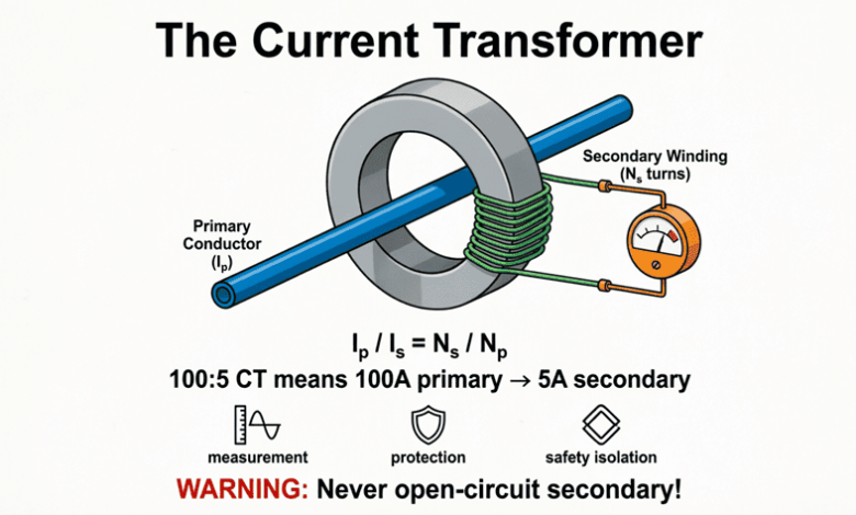
A current transformer (CT) is an instrument transformer that steps down high primary currents to standardized, safe secondary currents (typically 5A or 1A) for metering and protection. The secondary current is proportional to the primary current and is electrically isolated from the high-voltage primary circuit.
Construction and Operating Principle
Basic Construction
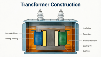
A current transformer consists of:
1. Primary Winding:
- Usually a single turn (bar-type or window-type CT)
- Connected in series with the line carrying the current to be measured
- Carries the full line current
- Low voltage rating (insulated for system voltage)
2. Secondary Winding:
- Many turns of fine wire
- Connected to measuring instruments or protective relays
- Standardized output: 5A or 1A (depending on standard)
- Must never be open-circuited when primary is energized
3. Magnetic Core:
- Made of high-permeability silicon steel or nickel-iron alloy
- Provides low-reluctance path for magnetic flux
- Designed for high accuracy at rated current
4. Insulation:
- Separates primary and secondary windings
- Withstands system voltage
- Oil-immersed or dry-type construction
Types of Current Transformers
1. Bar-Type CT:
- Primary is a solid copper or aluminum bar passing through the core
- Single-turn primary
- Common in switchgear and panel boards
- Easy to install
2. Window-Type (Ring-Type) CT:
- Toroidal core with no primary winding
- The line conductor itself acts as the primary turn
- Can be installed around existing conductors
- Very common for retrofits and monitoring
3. Wound-Type CT:
- Primary winding is wound on the core
- Multiple primary turns
- Used for low-ratio applications
- More expensive, less common
4. Bushing-Type CT:
- Mounted on transformer or circuit breaker bushings
- Uses the bushing conductor as primary
- Integrated design
Operating Principle
The current transformer operates on the same basic principle as a conventional transformer:
Primary Current ($I_p$) creates a magnetic flux in the core.
Secondary Current ($I_s$) is induced to oppose this flux (Lenz’s Law).
Ampere-Turn Balance:
In an ideal CT:
$I_p \times N_p = I_s \times N_s$
Where:
- $I_p$ = Primary current
- $N_p$ = Number of primary turns (usually 1)
- $I_s$ = Secondary current
- $N_s$ = Number of secondary turns
Since $N_p$ is typically 1:
$I_s = I_p \times \frac{N_p}{N_s} = \frac{I_p}{N_s}$
The secondary current is inversely proportional to the number of secondary turns.
Why must a CT secondary never be open-circuited?
When a CT secondary is open-circuited while primary current flows, there is no secondary current to oppose the primary flux. This causes the core to saturate, inducing dangerously high voltages (thousands of volts) across the open secondary terminals. This can cause insulation failure, arcing, fire, and severe electric shock hazards.
Current Transformer Ratio and Calculations
CT Ratio Definition
The CT ratio is the ratio of primary current to secondary current at rated conditions:
$\text{CT Ratio} = \frac{I_{p(rated)}}{I_{s(rated)}}$
Standard CT Ratios:
- 100:5, 200:5, 400:5, 600:5, 800:5, 1000:5, 1200:5, 1600:5, 2000:5, 3000:5, 4000:5
- Also available with 1A secondary: 100:1, 200:1, 400:1, etc.
Example:
A 400:5 CT means:
- Rated primary current: 400A
- Rated secondary current: 5A
- Ratio: 400/5 = 80:1
Calculating Secondary Current
For a given primary current:
$I_s = I_p \times \frac{I_{s(rated)}}{I_{p(rated)}} = \frac{I_p}{\text{CT Ratio}}$
Example:
CT Ratio: 600:5 (ratio = 120)
Primary current: 300A
$I_s = \frac{300}{120} = 2.5\text{A}$
Calculating Primary Current from Secondary
When measuring with a CT:
$I_p = I_s \times \frac{I_{p(rated)}}{I_{s(rated)}} = I_s \times \text{CT Ratio}$
Example:
CT Ratio: 1000:5 (ratio = 200)
Measured secondary current: 3.2A
$I_p = 3.2 \times 200 = 640\text{A}$
Multi-Ratio CTs
Some CTs have multiple taps on the secondary winding, allowing different ratios from a single CT:
Example:
A CT with secondary taps at 50%, 75%, and 100%:
- Full winding: 400:5
- 75% tap: 300:5
- 50% tap: 200:5
This provides flexibility for different load conditions or future expansion.
CT Accuracy Classes
Current transformers are classified by their accuracy, which defines how closely the secondary current matches the ideal proportional value.
Metering CTs
Metering CTs are designed for high accuracy at normal load currents (typically 5-120% of rated current). They are used for revenue metering and precision measurements.
Accuracy Class Designations (IEEE/ANSI):
- 0.1, 0.2, 0.3, 0.6, 1.2: The number indicates the maximum percentage ratio error at rated current.
Example:
- Class 0.3 CT: Maximum error of ±0.3% at rated current
- Used for revenue metering (billing)
Standard Accuracy Classes:
- 0.15S, 0.3S, 0.6S: “S” class CTs maintain accuracy over a wider range (1-120% of rated current)
- Used for high-precision metering
Protection CTs
Protection CTs are designed to maintain accuracy during fault conditions when currents can be 10-20 times the rated value. Accuracy at normal load is less critical.
Accuracy Class Designations (IEEE/ANSI):
- C (Calculated) Class: CTs with low leakage flux, accuracy can be calculated
- T (Tested) Class: CTs with higher leakage flux, must be tested
Common Classes:
- C100, C200, C400, C800: The number indicates the secondary terminal voltage the CT can deliver at 20 times rated secondary current without exceeding 10% ratio error.
Example:
- C200 CT: Can deliver 200V to the burden at 100A secondary current (20 × 5A) without exceeding 10% error.
IEC Standard Classes:
- 5P10, 5P20, 10P10, 10P20:
- First number (5 or 10): Maximum composite error percentage
- P: Protection
- Second number (10 or 20): Accuracy Limit Factor (ALF)
Example:
- 5P20: Maximum 5% error at 20 times rated current
What is the difference between metering and protection CTs?
Metering CTs are designed for high accuracy at normal load currents (5-120% of rated) and are used for billing and measurement. Protection CTs are designed to maintain accuracy during fault conditions (up to 20× rated current) and are used for protective relaying. Metering CTs saturate at high currents to protect instruments; protection CTs must NOT saturate during faults.
CT Burden and Saturation
CT Burden
Burden is the total impedance (resistance and reactance) connected to the CT secondary, including:
- Resistance of connecting wires
- Impedance of meters, relays, and instruments
- Contact resistance of terminals
Burden is expressed in:
- Volt-Amperes (VA) at rated secondary current
- Ohms (Ω) impedance
Standard Burden Ratings (IEEE):
- B-0.1, B-0.2, B-0.5, B-1.0, B-2.0, B-4.0 (in ohms)
- Or: 2.5 VA, 5 VA, 10 VA, 15 VA, 20 VA, 30 VA
Calculating Burden:
$S_{burden} = I_s^2 \times Z_{burden}$
Where:
- $S_{burden}$ = Burden in VA
- $I_s$ = Secondary current (typically 5A)
- $Z_{burden}$ = Total secondary impedance in ohms
Example:
CT secondary current: 5A
Total burden impedance: 0.4Ω
$S_{burden} = 5^2 \times 0.4 = 25 \times 0.4 = 10 \text{ VA}$
Effects of Excessive Burden
If the actual burden exceeds the CT’s rated burden:
- Accuracy decreases: Ratio error increases
- Phase angle error increases: Critical for power measurements
- CT may saturate: Especially during faults
- Protective relays may misoperate: False trips or failure to trip
CT Saturation
Saturation occurs when the CT core cannot support additional magnetic flux. This happens when:
- Primary current is too high (severe fault)
- Burden is too high (excessive impedance)
- DC offset in fault current (asymmetrical faults)
- Remanent flux in the core (residual magnetism)
Effects of Saturation:
- Secondary current becomes distorted (flattened waveform)
- Ratio error increases dramatically
- Protective relays may not operate correctly
- Metering becomes inaccurate
Preventing Saturation:
- Use CTs with higher accuracy class (C400 vs C200)
- Reduce burden (shorter wires, lower impedance devices)
- Use CTs with larger core cross-section
- Use air-gap cores for DC offset tolerance
CT Wiring and Connections
Polarity Markings
CTs have polarity markings to ensure correct connection:
Standard Markings:
- H1, H2: Primary terminals
- X1, X2: Secondary terminals
Polarity Convention:
- When primary current enters H1, secondary current leaves X1
- X1 is the “polarity” or “dot” terminal
- Critical for:
- Differential protection
- Power and energy metering
- Directional relaying
Polarity Test:
A simple DC test can verify polarity:
- Connect a DC battery and switch to primary
- Connect a DC voltmeter to secondary
- Close the switch momentarily
- If voltmeter kicks positive, polarity is correct (H1 to X1)
CT Secondary Connections
Never Open-Circuit a CT Secondary!
When a CT secondary is open while primary current flows:
- No opposing secondary current
- Core flux increases dramatically
- Core saturates
- Very high voltage induced (thousands of volts)
- DANGER: Electric shock, insulation failure, arcing, fire
Safety Rules:
- Always short-circuit the secondary before disconnecting instruments
- Use shorting terminals or test switches
- Never leave secondary open when primary is energized
- Ground one side of the secondary (usually X2) for safety
Grounding Requirements
One Point Grounding:
- CT secondary must be grounded at one point only
- Prevents multiple ground loops
- Usually grounded at the relay/meter panel
- Prevents high voltage buildup
Multiple CTs:
- If multiple CTs are connected (e.g., differential protection), ground at a single common point
- Prevents circulating currents
Practical Applications
1. Revenue Metering
CTs are essential for billing high-current loads:
- Residential services > 200A
- Commercial and industrial services
- Utility substations
Typical Setup:
- CT ratio: 400:5 or 800:5
- Accuracy class: 0.3S or 0.6S
- Connected to watt-hour meters
- Burden: < 2.5 VA
2. Protective Relaying
CTs provide current signals to protective relays:
Overcurrent Protection:
- Detects excessive current
- Trips circuit breaker
- CT class: C100 or C200
Differential Protection:
- Compares current entering and leaving a zone
- Detects internal faults
- Requires matched CTs with same ratio and accuracy
- CT class: C200 or C400
Distance Protection:
- Measures impedance to fault
- Requires accurate current and voltage
- CT class: C400 or higher
3. Ammeters and Indication
CTs provide scaled current for panel meters:
- Analog ammeters (0-5A scale)
- Digital meters
- SCADA systems
Typical Setup:
- CT ratio matched to ammeter scale
- Accuracy class: 1.2 or B-0.5
- Low burden requirement
4. Power Quality Monitoring
CTs provide current signals for:
- Harmonic analysis
- Power factor measurement
- Event recording
- Fault analysis
Requirements:
- Wide bandwidth (for harmonics)
- High accuracy
- Low phase angle error
5. Ground Fault Detection
Zero-Sequence CTs (Core Balance CTs):
- All three phase conductors pass through a single CT window
- Under normal conditions, sum of currents = 0
- During ground fault, unbalanced current flows
- CT detects ground fault current
- Very sensitive (can detect < 1A ground fault)
Practical Examples and Calculations
Example 1: CT Ratio Selection
Problem: A 480V industrial feeder has a maximum load current of 320A. Select an appropriate CT ratio for metering and calculate the secondary current at full load.
Solution:
Given:
- Maximum load: 320A
- Standard CT ratios available: 200:5, 300:5, 400:5, 600:5
Selection Criteria:
- CT rated current should be ≥ maximum load current
- For metering, optimal operation is 50-100% of rated current
- Choose next standard size above maximum load
Selection:
- 320A load requires CT rated ≥ 320A
- Choose 400:5 CT
Verification:
- At full load (320A): $320/400 = 80\%$ of rated ✓
- Good metering range
Secondary Current at Full Load:
CT Ratio = 400:5 = 80:1
$I_s = \frac{I_p}{\text{Ratio}} = \frac{320}{80} = 4.0\text{A}$
Result: Use 400:5 CT. At 320A load, secondary current is 4.0A.
Example 2: CT Burden Calculation
Problem: A 600:5 CT is connected to a relay with the following burden:
- Relay impedance: 0.2Ω
- Wire length: 50 feet (one way) of #12 AWG copper
- Contact resistance: 0.05Ω
Calculate the total burden in VA and determine if it exceeds the CT rating of 10 VA.
Solution:
Given:
- CT secondary current: 5A (rated)
- Relay impedance: 0.2Ω
- Wire: #12 AWG, 50 ft one way (100 ft total loop)
- Contact resistance: 0.05Ω
- CT rating: 10 VA
Step 1: Calculate Wire Resistance
12 AWG resistance: 1.588 Ω/1000 ft (at 75°C)
For 100 ft loop:
$R_{wire} = \frac{1.588 \times 100}{1000} = 0.1588 \Omega$
Step 2: Calculate Total Burden Impedance
$Z_{total} = R_{relay} + R_{wire} + R_{contact}$
$Z_{total} = 0.2 + 0.1588 + 0.05 = 0.4088 \Omega$
Step 3: Calculate Burden in VA
$S_{burden} = I_s^2 \times Z_{total}$
$S_{burden} = 5^2 \times 0.4088$
$S_{burden} = 25 \times 0.4088 = 10.22 \text{ VA}$
Step 4: Compare to CT Rating
Actual burden: 10.22 VA
CT rating: 10 VA
Result: The burden (10.22 VA) slightly exceeds the CT rating (10 VA).
Recommendations:
- Use larger wire (#10 AWG) to reduce resistance
- Or use a CT with higher burden rating (15 VA)
- Or reduce wire length if possible
Example 3: CT Saturation Check
Problem: A C200 CT with a 400:5 ratio is supplying a fault current of 8000A primary. The total secondary burden is 2.0Ω. Will the CT saturate?
Solution:
Given:
- CT class: C200
- CT ratio: 400:5 = 80:1
- Primary fault current: 8000A
- Secondary burden: 2.0Ω
Step 1: Calculate Secondary Current
$I_s = \frac{I_p}{\text{Ratio}} = \frac{8000}{80} = 100\text{A}$
(This is 20 times the rated 5A secondary current)
Step 2: Calculate Required Secondary Voltage
$V_s = I_s \times Z_{burden}$
$V_s = 100 \times 2.0 = 200\text{V}$
Step 3: Check Against CT Class
C200 CT can deliver 200V at 20 times rated current (100A) without exceeding 10% error.
Required voltage: 200V
CT capability: 200V
Result: The CT is operating at its limit. It should NOT saturate, but it will be at the edge of the 10% accuracy limit. For better performance, use a C400 CT or reduce the burden.
Conclusion
Current transformers are essential components in electrical power systems, providing safe, isolated, and proportional current signals for metering, protection, and control. Understanding CT operation, ratios, accuracy classes, and safety requirements is critical for electrical engineers.
Key takeaways from this guide:
- Construction: CTs have a single-turn (or few-turn) primary and multi-turn secondary, with standardized 5A or 1A secondary output.
- Ratio: CT ratio = Primary rated current / Secondary rated current. Secondary current is proportional to primary current.
- Accuracy Classes:
- Metering CTs (0.1, 0.2, 0.3S): High accuracy at normal loads
- Protection CTs (C100, C200, 5P20): Maintain accuracy during faults
- Burden: Total impedance connected to CT secondary. Must not exceed CT rating to maintain accuracy.
- Safety: NEVER open-circuit a CT secondary when primary is energized. Always short-circuit before disconnecting. Ground one point only.
- Saturation: Occurs when core flux exceeds capacity. Causes distortion and relay misoperation. Prevented by proper CT selection and burden management.
- Applications: Revenue metering, protective relaying, ammeters, power quality monitoring, ground fault detection.
- Polarity: Critical for differential protection and power metering. Must be verified during installation.
Mastering current transformer principles enables engineers to design accurate metering systems, reliable protection schemes, and safe electrical installations. Whether selecting CTs for a new substation or troubleshooting a protection relay, understanding CT behavior is fundamental to power system engineering.