Three Phase Transformers
Three Phase Transformers: Complete Guide to Connections & Configurations
Three-phase transformers are the backbone of modern electrical power systems, handling the generation, transmission, distribution, and utilization of electrical energy. While single-phase transformers serve residential and light commercial loads, three-phase transformers are essential for industrial facilities, power plants, substations, and the electrical grid itself.
A three-phase transformer can be constructed in two ways:
- Three-Phase Transformer Bank: Three single-phase transformers connected together
- Three-Phase Transformer Unit: A single unit with three sets of windings on a common core
Three-phase systems offer significant advantages over single-phase:
- Higher power density: More power for the same conductor size
- Constant power transfer: No power pulsations
- Efficient motor operation: Self-starting three-phase motors
- Economical transmission: Less conductor material for same power
Understanding three-phase transformer connections, phase relationships, and voltage transformations is fundamental for electrical engineers working with power systems, industrial facilities, and electrical distribution.
This comprehensive guide will explore three-phase transformer construction, connection configurations (Delta and Wye), phase relationships, voltage and current calculations, and practical applications.
What is a three-phase transformer?
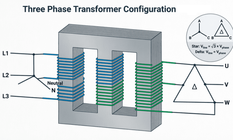
A three-phase transformer is a transformer designed to handle three-phase AC power. It can be built as a bank of three single-phase transformers or as a single unit with three windings on a common core. The windings can be connected in Delta (Δ) or Wye (Y) configurations, providing different voltage relationships and phase shifts.
Construction of Three Phase Transformers
Three-Phase Transformer Bank
A three-phase transformer bank consists of three separate single-phase transformers connected together to handle three-phase power.
Advantages:
- Flexibility: Can operate with one transformer removed (open-delta)
- Spare inventory: Only need one spare single-phase unit
- Transportation: Easier to transport smaller units
- Maintenance: Can service one transformer while others operate
Disadvantages:
- Larger size: More total core and copper material
- Higher cost: More expensive than a single three-phase unit
- More connections: More complex wiring
Three-Phase Transformer Unit
A three-phase transformer unit has all three phases built into a single tank with a common core structure.
Core Configurations:
1. Core-Type:
- Three vertical limbs connected by top and bottom yokes
- Each limb carries primary and secondary windings of one phase
- Most common construction
- Better cooling
2. Shell-Type:
- Central limb with two outer limbs
- Windings on central limb
- Better mechanical strength
- Less common
Advantages:
- Compact: Smaller size and weight
- Lower cost: Less material required
- Higher efficiency: Lower losses
- Simpler installation: Fewer external connections
Disadvantages:
- Single point of failure: Entire unit out if one phase fails
- Spare requirements: Must stock complete three-phase unit
- Transportation: Heavier and more difficult to move
What is the difference between a three-phase transformer bank and a three-phase transformer unit?
A three-phase transformer bank uses three separate single-phase transformers connected together, offering flexibility and easier maintenance. A three-phase transformer unit is a single device with all three phases on a common core, offering better efficiency, lower cost, and smaller size but less flexibility.
Three-Phase Connection Configurations
Three-phase transformers can have their primary and secondary windings connected in various combinations of Delta (Δ) and Wye (Y). The four standard configurations are:
1. Delta-Delta (Δ-Δ) Connection
Primary: Delta-connected
Secondary: Delta-connected
Characteristics:
- No phase shift between primary and secondary
- Line voltage = Phase voltage
- Line current = √3 × Phase current
- Third harmonic currents circulate within delta
- Can operate with one transformer removed (open-delta at 58% capacity)
Applications:
- Industrial loads
- Balanced three-phase loads
- Where continuity of service is important
Advantages:
- No neutral required
- Handles unbalanced loads well
- Third harmonic suppression
- Reliable (open-delta operation possible)
Disadvantages:
- No neutral for single-phase loads
- Higher insulation requirements (line voltage across windings)
2. Wye-Wye (Y-Y) Connection
Primary: Wye-connected
Secondary: Wye-connected
Characteristics:
- No phase shift between primary and secondary
- Line voltage = 3 × Phase voltage
- Line current = Phase current
- Neutral available on both sides
- Requires neutral grounding or tertiary delta
Applications:
- High-voltage transmission
- Where neutral is needed on both sides
- Small high-voltage transformers
Advantages:
- Neutral available for grounding
- Lower insulation requirements (phase voltage across windings)
- Can supply single-phase loads
Disadvantages:
- Third harmonic problems (requires neutral connection or tertiary winding)
- Unbalanced load causes neutral shift
- Not commonly used without tertiary delta
3. Delta-Wye (Δ-Y) Connection
Primary: Delta-connected
Secondary: Wye-connected
Characteristics:
- 30° phase shift (secondary lags primary by 30°)
- Secondary line voltage = √3 × Secondary phase voltage
- Neutral available on secondary
- Most common configuration
Applications:
- Step-down distribution transformers (most common)
- Utility distribution substations
- Commercial and industrial facilities
- Where neutral is needed for single-phase loads
Advantages:
- Neutral available for single-phase loads
- Lower insulation on secondary (phase voltage)
- Third harmonic suppression (delta primary)
- Good for unbalanced loads
- Standard for distribution
Disadvantages:
- 30° phase shift (must be considered in parallel operation)
- Cannot be paralleled with Δ-Δ or Y-Y without phase shift compensation
4. Wye-Delta (Y-Δ) Connection
Primary: Wye-connected
Secondary: Delta-connected
Characteristics:
- 30° phase shift (secondary leads primary by 30°)
- Primary line voltage = √3 × Primary phase voltage
- No neutral on secondary
Applications:
- Step-up transformers at generating stations
- Transmission substations
- Where delta secondary is needed
Advantages:
- Lower insulation on primary (phase voltage)
- Neutral available on primary for grounding
- Third harmonic suppression (delta secondary)
Disadvantages:
- 30° phase shift
- No neutral on secondary for single-phase loads
What is the most common three-phase transformer connection?
The Delta-Wye (Δ-Y) connection is the most common for distribution transformers. The delta primary suppresses third harmonics, while the wye secondary provides a neutral for single-phase loads. There is a 30° phase shift between primary and secondary.
Voltage and Current Relationships
Delta Connection
Voltage:
- Line voltage = Phase voltage
- $V_L = V_{ph}$
Current:
- Line current = 3 × Phase current
- $I_L = \sqrt{3} \times I_{ph}$
- Line current lags phase current by 30°
Power:
- $S = \sqrt{3} \times V_L \times I_L$
- $P = \sqrt{3} \times V_L \times I_L \times \cos\phi$
Wye Connection
Voltage:
- Line voltage = √3 × Phase voltage
- $V_L = \sqrt{3} \times V_{ph}$
- Line voltage leads phase voltage by 30°
Current:
- Line current = Phase current
- $I_L = I_{ph}$
Power:
- $S = \sqrt{3} \times V_L \times I_L$
- $P = \sqrt{3} \times V_L \times I_L \times \cos\phi$
Phase Shift in Delta-Wye Transformers
In Delta-Wye and Wye-Delta connections, there is a 30° phase shift between primary and secondary line voltages.
Delta-Wye (Δ-Y):
- Secondary voltage lags primary voltage by 30°
- Standard for step-down distribution
Wye-Delta (Y-Δ):
- Secondary voltage leads primary voltage by 30°
- Standard for step-up at generating stations
Phase Shift Importance:
- Critical for parallel operation
- Must match phase shifts when paralleling transformers
- Affects protective relay coordination
- Important for motor rotation
Practical Applications
1. Power Generation
Generator Step-Up Transformers:
- Configuration: Wye-Delta (Y-Δ)
- Primary (generator side): Wye-connected for neutral grounding
- Secondary (transmission side): Delta-connected
- Voltage: 13.8-25 kV to 138-765 kV
- Purpose: Step up voltage for efficient transmission
2. Transmission Substations
Interconnection Transformers:
- Configuration: Delta-Wye or Wye-Wye with tertiary
- Connect different transmission voltage levels
- Example: 230 kV to 138 kV
- Provide system grounding
3. Distribution Substations
Distribution Transformers:
- Configuration: Delta-Wye (Δ-Y) – most common
- Primary: Delta (distribution voltage: 4-35 kV)
- Secondary: Wye (utilization voltage: 120/208V or 277/480V)
- Provide neutral for single-phase loads
- Suppress third harmonics
4. Industrial Facilities
Service Transformers:
- Configuration: Delta-Wye or Delta-Delta
- Voltage: 480V, 600V, 2400V, 4160V
- Supply motors and industrial loads
- Delta-Delta for balanced three-phase loads
- Delta-Wye when neutral needed
5. Commercial Buildings
Building Service Transformers:
- Configuration: Delta-Wye (Δ-Y)
- Primary: 4-35 kV from utility
- Secondary: 120/208V or 277/480V
- Supply lighting, HVAC, and receptacles
- Neutral for single-phase loads
Practical Examples and Calculations
Example 1: Delta-Wye Transformer Voltage Calculation
Problem: A 1500 kVA, 13.8 kV/480Y/277V three-phase transformer is connected Delta-Wye. Calculate:
- Primary phase voltage
- Secondary phase voltage
- Primary line current at full load
- Secondary line current at full load
Solution:
Given:
- Rating: 1500 kVA
- Primary: 13.8 kV (Delta)
- Secondary: 480Y/277V (Wye)
1. Primary Phase Voltage (Delta):
For Delta connection: $V_{ph} = V_L$
$V_{ph(primary)} = 13.8 \text{ kV}$
2. Secondary Phase Voltage (Wye):
For Wye connection: $V_{ph} = V_L / \sqrt{3}$
$V_{ph(secondary)} = 480 / \sqrt{3} = 480 / 1.732 = 277 \text{ V}$
3. Primary Line Current:
$S = \sqrt{3} \times V_L \times I_L$
$I_L = S / (\sqrt{3} \times V_L)$
$I_{L(primary)} = 1,500,000 / (\sqrt{3} \times 13,800)$
$I_{L(primary)} = 1,500,000 / 23,904 = 62.75 \text{ A}$
4. Secondary Line Current:
$I_{L(secondary)} = 1,500,000 / (\sqrt{3} \times 480)$
$I_{L(secondary)} = 1,500,000 / 831.4 = 1,804 \text{ A}$
Result:
- Primary phase voltage: 13.8 kV
- Secondary phase voltage: 277V
- Primary line current: 62.75A
- Secondary line current: 1,804A
Example 2: Transformer Bank Configuration
Problem: Three single-phase transformers, each rated 100 kVA, 7200/240V, are connected to form a three-phase bank. Calculate the three-phase rating and line voltages for:
- Delta-Delta connection
- Wye-Wye connection
- Delta-Wye connection
Solution:
Given:
- Single-phase rating: 100 kVA each
- Voltage ratio: 7200/240V
- Three transformers
Three-Phase Rating:
$S_{3\phi} = 3 \times S_{1\phi} = 3 \times 100 = 300 \text{ kVA}$
1. Delta-Delta Connection:
Primary (Delta):
- Line voltage = Phase voltage = 7200V
- $V_{L(primary)} = 7200 \text{ V}$
Secondary (Delta):
- Line voltage = Phase voltage = 240V
- $V_{L(secondary)} = 240 \text{ V}$
Configuration: 7200V Δ / 240V Δ
2. Wye-Wye Connection:
Primary (Wye):
- Phase voltage = 7200V
- Line voltage = $\sqrt{3} \times 7200 = 12,470 \text{ V}$
- $V_{L(primary)} = 12.47 \text{ kV}$
Secondary (Wye):
- Phase voltage = 240V
- Line voltage = $\sqrt{3} \times 240 = 416 \text{ V}$
- $V_{L(secondary)} = 416 \text{ V}$
Configuration: 12.47 kV Y / 416Y/240V
3. Delta-Wye Connection:
Primary (Delta):
- Line voltage = Phase voltage = 7200V
- $V_{L(primary)} = 7200 \text{ V}$
Secondary (Wye):
- Phase voltage = 240V
- Line voltage = $\sqrt{3} \times 240 = 416 \text{ V}$
- $V_{L(secondary)} = 416 \text{ V}$
- Neutral available
Configuration: 7200V Δ / 416Y/240V
Result:
- Delta-Delta: 7200V/240V
- Wye-Wye: 12.47 kV/416V
- Delta-Wye: 7200V/416Y/240V (most common for distribution)
Example 3: Open-Delta Operation
Problem: A Delta-Delta transformer bank consists of three 50 kVA single-phase transformers. If one transformer fails and is removed, calculate:
- The remaining capacity in open-delta
- The percentage of original capacity
- The line currents if the bank supplies a 100 kVA load
Solution:
Given:
- Original bank: 3 × 50 kVA = 150 kVA
- One transformer removed
- Load: 100 kVA
1. Open-Delta Capacity:
In open-delta (V-V) connection, capacity is reduced to 57.7% (or $1/\sqrt{3}$) of original:
$S_{open} = S_{original} / \sqrt{3}$
$S_{open} = 150 / 1.732 = 86.6 \text{ kVA}$
Alternatively:
$S_{open} = 2 \times 50 \times 0.866 = 86.6 \text{ kVA}$
2. Percentage of Original Capacity:
$\% \text{ Capacity} = (86.6 / 150) \times 100\% = 57.7\%$
3. Line Currents with 100 kVA Load:
Since 100 kVA > 86.6 kVA capacity, the transformers are overloaded.
Overload percentage: $(100 / 86.6) \times 100\% = 115.5\%$
Each transformer carries: $100 / 2 = 50 \text{ kVA}$ (at rated voltage)
This is exactly the rated capacity of each transformer, but in open-delta, the phase relationships cause each transformer to carry more than its proportional share.
Result:
- Open-delta capacity: 86.6 kVA
- Percentage: 57.7% of original
- With 100 kVA load: Transformers are overloaded (not recommended for continuous operation)
Three-phase transformers are essential components of modern electrical power systems, providing efficient voltage transformation for generation, transmission, distribution, and utilization of electrical energy.
Key takeaways from this guide:
- Construction:
- Three-phase bank: Three single-phase transformers (flexible, larger)
- Three-phase unit: Single device (compact, efficient)
- Connection Configurations:
- Delta-Delta (Δ-Δ): No phase shift, no neutral, reliable
- Wye-Wye (Y-Y): Neutral available, third harmonic issues
- Delta-Wye (Δ-Y): 30° shift, neutral on secondary, most common for distribution
- Wye-Delta (Y-Δ): 30° shift, neutral on primary, common for step-up
- Voltage Relationships:
- Delta: $V_L = V_{ph}$, $I_L = \sqrt{3} \times I_{ph}$
- Wye: $V_L = \sqrt{3} \times V_{ph}$, $I_L = I_{ph}$
- Phase Shift:
- Δ-Y: Secondary lags by 30°
- Y-Δ: Secondary leads by 30°
- Critical for parallel operation
- Applications:
- Generation: Y-Δ step-up
- Transmission: Various configurations
- Distribution: Δ-Y (most common)
- Industrial: Δ-Δ or Δ-Y
- Open-Delta Operation:
- Can operate with one transformer removed
- Capacity reduced to 57.7% of original
- Emergency operation only
Mastering three-phase transformer connections and calculations is essential for electrical engineers working with power systems, industrial facilities, and electrical distribution. Whether designing a new substation, selecting service transformers, or troubleshooting three-phase systems, understanding these principles is fundamental to electrical engineering practice.