Transformer Testing and Efficiency

Transformer Testing and Efficiency: The Complete Guide to OC, SC Tests & Losses
Transformers are the workhorses of the electrical power system, designed to operate reliably for decades with minimal maintenance. However, to ensure they perform as expected, operate efficiently, and do not pose a safety hazard, rigorous transformer testing is required both at the factory and throughout their operational life.
Furthermore, because transformers operate continuously, even small inefficiencies translate into massive energy losses and increased operating costs over time. Understanding transformer efficiency, the different types of losses, and how to calculate them is crucial for electrical engineers, facility managers, and utility operators.
This comprehensive guide will explore the fundamental tests used to characterize transformer performance (Open-Circuit and Short-Circuit tests), routine field tests (Polarity, Turns Ratio, Insulation Resistance), advanced diagnostic techniques like Dissolved Gas Analysis (DGA), and the mathematical principles governing transformer efficiency.
Why do we test transformers?
Transformer testing is performed to verify performance specifications (like efficiency and impedance), ensure safety (insulation integrity), and detect early signs of internal degradation (like overheating or arcing). Key tests include the Open-Circuit test for core losses, the Short-Circuit test for copper losses, and routine field tests like Turns Ratio and Insulation Resistance.
Transformer Efficiency and Losses
Transformer efficiency ($\eta$) is the ratio of useful output power to the total input power. Because transformers are static devices with no rotating parts, they are highly efficient, typically ranging from 95% to 99.5%.
$\eta = \frac{P_{out}}{P_{in}} \times 100\% = \frac{P_{out}}{P_{out} + P_{losses}} \times 100\%$
Types of Transformer Losses
Transformer losses are categorized into two main types:
1. Core Losses (Iron Losses, $P_{core}$):
These are constant losses that occur whenever the transformer is energized, regardless of the load. They consist of:
- Hysteresis Loss: Energy lost due to the continuous reversal of magnetic domains in the core material. Minimized by using grain-oriented silicon steel.
- Eddy Current Loss: Circulating currents induced within the core laminations. Minimized by using thin, insulated laminations.
2. Copper Losses ($P_{copper}$):
These are variable losses that depend on the load current. They are caused by the electrical resistance of the primary and secondary windings.
- Formula: $P_{copper} = I_1^2 R_1 + I_2^2 R_2$
- Also known as $I^2R$ losses. At a load fraction $x$ (where $x=1$ is full load), copper losses are $x^2 \times P_{copper(full-load)}$.
Condition for Maximum Efficiency
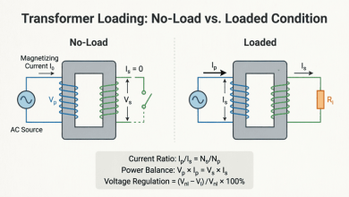
A transformer does not operate at maximum efficiency at full load. Maximum efficiency occurs when the variable losses equal the constant losses:
$P_{copper} = P_{core}$
To find the load fraction ($x$) at which maximum efficiency occurs:
$x = \sqrt{\frac{P_{core}}{P_{copper(full-load)}}}$
Example: If core losses are 400W and full-load copper losses are 1600W, maximum efficiency occurs at $x = \sqrt{400/1600} = \sqrt{0.25} = 0.5$ (or 50% load).
All-Day Efficiency
For distribution transformers that are energized 24/7 but experience widely varying loads (e.g., light load at night, heavy load during the day), all-day efficiency is a more meaningful metric than commercial efficiency at a single point.
$\eta_{all-day} = \frac{\text{Total Energy Output in 24 hours (kWh)}}{\text{Total Energy Input in 24 hours (kWh)}} \times 100\%$
Because core losses occur continuously, distribution transformers are specifically designed to have very low core losses, even if it means slightly higher copper losses, to maximize all-day efficiency.
When does a transformer achieve maximum efficiency?
A transformer achieves maximum efficiency when its variable copper losses exactly equal its constant core (iron) losses. For most distribution transformers, this occurs between 40% and 70% of full load.
Fundamental Transformer Tests
To determine the equivalent circuit parameters and losses without actually loading the transformer to its full capacity, two standard tests are performed: the Open-Circuit (OC) test and the Short-Circuit (SC) test.
1. Open-Circuit (OC) Test
Purpose: To determine core losses ($P_{core}$), no-load current ($I_0$), and the shunt branch parameters of the equivalent circuit (magnetizing reactance $X_m$ and core loss resistance $R_c$).
Procedure:
- The Low-Voltage (LV) side is connected to the rated voltage and frequency.
- The High-Voltage (HV) side is left open-circited.
- A voltmeter, ammeter, and wattmeter are connected to the LV side.
Why LV side? It is safer and easier to apply rated voltage to the LV side. The no-load current is very small (2-5% of rated current), so copper losses on the LV side are negligible. Therefore, the wattmeter reading represents almost entirely the core losses.
Calculations:
- $P_{core} = W_{OC}$ (Wattmeter reading)
- No-load power factor: $\cos\phi_0 = \frac{W_{OC}}{V_{OC} \times I_{OC}}$
- Core loss component of current: $I_c = I_{OC} \cos\phi_0$
- Magnetizing component of current: $I_m = I_{OC} \sin\phi_0$
- Core resistance: $R_c = \frac{V_{OC}}{I_c}$
- Magnetizing reactance: $X_m = \frac{V_{OC}}{I_m}$
2. Short-Circuit (SC) Test
Purpose: To determine full-load copper losses ($P_{cu}$), equivalent resistance ($R_{eq}$), equivalent leakage reactance ($X_{eq}$), and percentage impedance ($\%Z$).
Procedure:
- The High-Voltage (HV) side is connected to a variable low-voltage AC source.
- The Low-Voltage (LV) side is short-circuited with a thick conductor.
- The applied voltage is slowly increased until the rated full-load current flows in the HV winding. (This voltage is typically only 5-10% of the rated voltage).
- A voltmeter, ammeter, and wattmeter are connected to the HV side.
Why HV side? The rated current is lower on the HV side, making it easier to measure with standard instruments. Because the applied voltage is very low, the core flux is minimal, meaning core losses are negligible. The wattmeter reading represents almost entirely the full-load copper losses.
Calculations:
- $P_{cu(full-load)} = W_{SC}$ (Wattmeter reading)
- Equivalent impedance (referred to HV): $Z_{eq} = \frac{V_{SC}}{I_{SC}}$
- Equivalent resistance (referred to HV): $R_{eq} = \frac{W_{SC}}{I_{SC}^2}$
- Equivalent reactance (referred to HV): $X_{eq} = \sqrt{Z_{eq}^2 – R_{eq}^2}$
- Percentage Impedance: $\%Z = \frac{V_{SC}}{V_{rated(HV)}} \times 100\%$
Routine Field and Diagnostic Tests
Beyond OC and SC tests, several routine tests ensure a transformer is safe and correctly configured for installation.
1. Polarity Test
Determines the relative direction of induced voltages in the primary and secondary windings.
- Subtractive Polarity: Standard for most transformers. The voltage between adjacent primary and secondary terminals is the difference of their voltages.
- Additive Polarity: The voltage is the sum.
Crucial for: Connecting transformers in parallel or in three-phase banks. Incorrect polarity causes a dead short circuit.
2. Turns Ratio Test (TTR)
Applies a low voltage to the primary and measures the secondary voltage to verify the turns ratio. A deviation of more than ±0.5% from the nameplate ratio indicates shorted turns or tap changer issues.
3. Insulation Resistance Test (Megger Test)
Uses a high-voltage DC tester (Megohmmeter) to measure the resistance between:
- Windings and ground (core/tank)
- Primary and secondary windings
Low resistance indicates moisture ingress, contamination, or insulation breakdown.
4. Dissolved Gas Analysis (DGA)
The most powerful diagnostic tool for oil-filled transformers. Faults like arcing, overheating, or partial discharge decompose the insulating oil, generating specific gases (Hydrogen, Methane, Ethylene, Acetylene, Carbon Monoxide).
- High Acetylene ($C_2H_2$): Indicates arcing.
- High Ethylene ($C_2H_4$): Indicates severe overheating.
- High Carbon Monoxide (CO): Indicates cellulose (paper) insulation degradation.
Practical Examples and Calculations
Example 1: Calculating Efficiency from Test Data
Problem: A 100 kVA, 2400/240V single-phase transformer undergoes testing.
- OC Test (LV side): 240V, 4.5A, 400W
- SC Test (HV side): 120V, 41.67A, 1200W
Calculate the efficiency of the transformer at 75% of full load and 0.8 lagging power factor.
Solution:
Step 1: Identify Losses
- Core Loss ($P_{core}$) = OC Wattmeter reading = 400 W
- Full-Load Copper Loss ($P_{cu,FL}$) = SC Wattmeter reading = 1200 W
Step 2: Calculate Output Power at 75% Load
Load fraction $x = 0.75$
$P_{out} = x \times S_{rated} \times \cos\phi$
$P_{out} = 0.75 \times 100,000 \text{ VA} \times 0.8 = \mathbf{60,000 \text{ W}}$
Step 3: Calculate Copper Loss at 75% Load
$P_{cu} = x^2 \times P_{cu,FL}$
$P_{cu} = (0.75)^2 \times 1200 = 0.5625 \times 1200 = \mathbf{675 \text{ W}}$
Step 4: Calculate Total Losses
$P_{losses} = P_{core} + P_{cu} = 400 + 675 = \mathbf{1075 \text{ W}}$
Step 5: Calculate Efficiency
$\eta = \frac{P_{out}}{P_{out} + P_{losses}} \times 100\%$
$\eta = \frac{60,000}{60,000 + 1075} \times 100\%$
$\eta = \frac{60,000}{61,075} \times 100\% = \mathbf{98.24\%}$
Result: The transformer efficiency at 75% load and 0.8 PF is 98.24%.
Example 2: Determining Equivalent Circuit Parameters
Problem: Using the data from Example 1, calculate the equivalent resistance ($R_{eq}$) and equivalent reactance ($X_{eq}$) referred to the High-Voltage side.
Solution:
Given from SC Test (HV side):
- $V_{SC} = 120\text{V}$
- $I_{SC} = 41.67\text{A}$ (This is the rated HV current: $100,000 / 2400 = 41.67\text{A}$)
- $W_{SC} = 1200\text{W}$
Step 1: Calculate Equivalent Impedance ($Z_{eq}$)
$Z_{eq} = \frac{V_{SC}}{I_{SC}} = \frac{120}{41.67} = \mathbf{2.88 \ \Omega}$
Step 2: Calculate Equivalent Resistance ($R_{eq}$)
$R_{eq} = \frac{W_{SC}}{I_{SC}^2} = \frac{1200}{(41.67)^2} = \frac{1200}{1736.4} = \mathbf{0.69 \ \Omega}$
Step 3: Calculate Equivalent Reactance ($X_{eq}$)
$X_{eq} = \sqrt{Z_{eq}^2 – R_{eq}^2}$
$X_{eq} = \sqrt{2.88^2 – 0.69^2} = \sqrt{8.29 – 0.48} = \sqrt{7.81} = \mathbf{2.79 \ \Omega}$
Result: Referred to the HV side, $R_{eq} = 0.69 \ \Omega$ and $X_{eq} = 2.79 \ \Omega$.
Transformer testing and efficiency analysis are foundational practices in electrical engineering, ensuring that power systems operate safely, reliably, and economically. By understanding the distinct nature of core and copper losses, engineers can optimize transformer loading and select the right equipment for specific duty cycles.
Key takeaways from this guide:
- Efficiency: Governed by constant core losses and variable copper losses ($I^2R$). Maximum efficiency occurs when $P_{core} = P_{copper}$.
- Open-Circuit (OC) Test: Performed on the LV side with the HV side open. Measures core losses and determines shunt branch parameters ($R_c, X_m$).
- Short-Circuit (SC) Test: Performed on the HV side with the LV side shorted. Measures full-load copper losses and determines series branch parameters ($R_{eq}, X_{eq}, \%Z$).
- Routine Tests: Polarity, Turns Ratio (TTR), and Insulation Resistance (Megger) tests are mandatory before energizing a new or refurbished transformer.
- Diagnostics: Dissolved Gas Analysis (DGA) is the gold standard for detecting internal faults like arcing, overheating, and insulation degradation in oil-filled transformers.
- All-Day Efficiency: The critical metric for distribution transformers, emphasizing the need for low core losses due to 24/7 energization.
Mastering these testing methodologies and efficiency calculations empowers engineers to validate transformer performance, troubleshoot operational issues, and implement predictive maintenance strategies that extend equipment life and prevent catastrophic failures.