Transformer Loading
Transformer Loading: Complete Guide to Load Characteristics and Effects
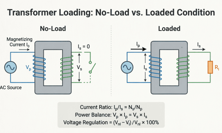
Transformer loading refers to the amount of electrical power drawn from the transformer secondary winding by connected loads. Understanding loading characteristics is crucial for proper transformer selection, efficient operation, thermal management, and longevity. Unlike ideal transformers that can handle any load, real transformers have specific ratings and limitations that must be respected to ensure reliable operation and prevent damage.
The loading of a transformer affects virtually every aspect of its performance:
- Efficiency: Varies with load level
- Temperature rise: Increases with loading
- Voltage regulation: Degrades under heavy loads
- Losses: Both copper and core losses change with load
- Life expectancy: Overloading reduces transformer life
- Power quality: Heavy loads can cause voltage drops and harmonics
Proper load management ensures transformers operate within their design limits while maintaining optimal efficiency and reliability. This comprehensive guide will explore all aspects of transformer loading, from basic concepts to advanced load management techniques.
What is transformer loading?
Transformer loading refers to the amount of power (kVA) drawn from the transformer by connected loads. Transformers are rated for a specific kVA capacity at rated voltage and frequency. Loading affects efficiency, temperature rise, voltage regulation, and transformer life. Optimal loading is typically 50-80% of rated capacity for best efficiency and longevity.
Types of Transformer Loads
Transformers can supply various types of loads, each with different characteristics that affect transformer performance differently.
1. Resistive Loads
Characteristics:
- Power factor = 1.0 (unity)
- Current in phase with voltage
- Purely real power consumption
- No reactive power
Examples:
- Incandescent lighting
- Electric heaters
- Resistance furnaces
- Toasters, electric stoves
Impact on Transformer:
- Most efficient operation
- Minimum voltage drop
- Lowest temperature rise for given kVA
- No reactive power demand
Calculation:
$P = V \times I$ (watts)
$S = P$ (VA = W at unity PF)
2. Inductive Loads
Characteristics:
- Lagging power factor (0 < PF < 1)
- Current lags voltage
- Consumes reactive power (Q > 0)
- Most common load type
Examples:
- Induction motors
- Transformers (downstream)
- Fluorescent lighting (magnetic ballasts)
- Welding equipment
- Solenoids and relays
Impact on Transformer:
- Reduced efficiency
- Higher voltage drop
- Increased temperature rise
- Requires larger kVA rating for same real power
- May require power factor correction
Calculation:
$P = V \times I \times \cos\phi$ (real power)
$Q = V \times I \times \sin\phi$ (reactive power)
$S = V \times I$ (apparent power)
$S = \sqrt{P^2 + Q^2}$
3. Capacitive Loads
Characteristics:
- Leading power factor (0 < PF < 1)
- Current leads voltage
- Supplies reactive power (Q < 0)
- Less common as primary load
Examples:
- Capacitor banks (for power factor correction)
- Long transmission lines (capacitive effect)
- Underground cables
- Electronic power supplies (input filters)
Impact on Transformer:
- Can improve overall system power factor
- May cause voltage rise (Ferranti effect)
- Can create resonance with system inductance
- Generally beneficial when properly applied
4. Non-Linear Loads
Characteristics:
- Draw non-sinusoidal current
- Generate harmonic currents
- Distorted waveform
- Increasingly common in modern systems
Examples:
- Variable frequency drives (VFDs)
- Switch-mode power supplies
- LED drivers
- Computers and data centers
- Rectifiers and inverters
- Arc furnaces
Impact on Transformer:
- Increased heating (harmonic losses)
- Reduced efficiency
- Possible resonance issues
- May require derating (K-factor transformers)
- Neutral current can exceed phase current (triplen harmonics)
Harmonic Effects:
- Eddy current losses increase with frequency squared
- Skin effect increases conductor resistance
- Core losses may increase
- Requires special consideration in transformer design
What is the difference between resistive and inductive loading?
Resistive loads have unity power factor (current in phase with voltage) and consume only real power. Inductive loads have lagging power factor (current lags voltage) and consume both real and reactive power. Inductive loads cause greater voltage drop and require larger transformer kVA ratings for the same real power output.
Load Effects on Transformer Performance
Efficiency Variation with Load
Transformer efficiency is not constant—it varies significantly with load level.
Efficiency Formula:
$\eta = \frac{P_{out}}{P_{in}} \times 100\% = \frac{P_{out}}{P_{out} + P_{losses}} \times 100\%$
Losses:
- Core/Iron Losses (P_core): Constant regardless of load
- Hysteresis loss
- Eddy current loss
- Present whenever transformer is energized
- Copper Losses (P_copper): Vary with load current squared
- $P_{copper} = I^2R$
- Zero at no-load
- Increase rapidly with load
Efficiency at Different Loads:
At load fraction $x$ (where $x = 1$ is full load):
$\eta = \frac{x \times S_{rated} \times \cos\phi}{x \times S_{rated} \times \cos\phi + P_{core} + x^2 \times P_{copper(full)}} \times 100\%$
Where:
- $x$ = Load fraction (0 to 1+)
- $S_{rated}$ = Rated kVA
- $\cos\phi$ = Load power factor
- $P_{core}$ = Core losses (constant)
- $P_{copper(full)}$ = Full-load copper losses
Maximum Efficiency Condition:
Maximum efficiency occurs when:
Variable losses = Constant losses
$x^2 \times P_{copper(full)} = P_{core}$
Solving for $x$:
$x = \sqrt{\frac{P_{core}}{P_{copper(full)}}}$
Example: If $P_{core} = 100W$ and $P_{copper(full)} = 400W$:
$x = \sqrt{100/400} = \sqrt{0.25} = 0.5$
Maximum efficiency occurs at 50% load.
Typical Efficiency Curve:
- No-load: 0% efficiency (output = 0)
- Light load (10-25%): Low efficiency (core losses dominate)
- Medium load (40-75%): High efficiency (optimal range)
- Full load (100%): Good efficiency
- Overload (>100%): Decreasing efficiency (copper losses dominate)
Temperature Rise with Loading
Transformer temperature rise is directly related to loading and is a critical factor in transformer life.
Heat Generation:
Total heat generated = Core losses + Copper losses
Heat Transfer:
- Heat transfers from windings to oil (or air)
- Oil circulates and transfers heat to tank/radiators
- Tank/radiators dissipate heat to ambient air
Temperature Rise Components:
- Average Winding Rise:
- Temperature rise of winding above ambient
- Typically 55-65°C for oil-filled transformers
- 80-150°C for dry-type (depending on insulation class)
- Top Oil Rise:
- Temperature rise of oil at top of tank
- Typically 45-55°C above ambient
- Oil temperature varies (hotter at top)
- Hot-Spot Temperature:
- Hottest point in winding
- Typically 10-15°C above average winding temperature
- Critical for insulation life
Temperature Rise Formula:
Temperature rise is proportional to losses:
$\Delta T \propto (P_{core} + x^2 \times P_{copper})$
Where $x$ = load fraction
Approximate Relationship:
At full load: $\Delta T_{full}$
At load $x$: $\Delta T \approx \Delta T_{full} \times x^{1.6}$ to $x^{2.0}$
(The exponent varies based on cooling method)
Impact on Insulation Life:
Insulation life follows the Arrhenius equation: Life halves for every 8-10°C increase in temperature.
Rule of Thumb:
- Operate at rated temperature: Normal life (20-30 years)
- +8°C above rated: Life reduced by 50%
- +16°C above rated: Life reduced by 75%
- Continuous overloading dramatically reduces life
Example:
A transformer with 65°C average winding rise:
- At 100% load: 65°C rise, normal life
- At 120% load: ~94°C rise (65 × 1.2^1.8), life reduced significantly
- At 150% load: ~140°C rise, rapid degradation
Voltage Regulation Under Load
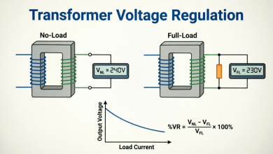
Voltage regulation is the change in secondary voltage from no-load to full-load.
Definition:
$\% \text{Regulation} = \frac{V_{no-load} – V_{full-load}}{V_{full-load}} \times 100\%$
Or:
$\% \text{Regulation} = \frac{V_{NL} – V_{FL}}{V_{FL}} \times 100\%$
Causes of Voltage Drop:
- Winding Resistance:
- $I \times R$ voltage drop
- In phase with current
- Leakage Reactance:
- $I \times X$ voltage drop
- 90° out of phase with current
Approximate Regulation Formula:
$\% \text{Reg} \approx x \times [(R\% \times \cos\phi) + (X\% \times \sin\phi)]$
Where:
- $x$ = Load fraction
- $R\%$ = Percentage resistance
- $X\%$ = Percentage reactance
- $\cos\phi$ = Load power factor
- $\sin\phi$ = Reactive factor
Power Factor Effect:
Lagging PF (inductive load):
- Positive regulation (voltage drops)
- Worse at lower PF
- Example: 0.8 lagging → 3-5% regulation
Unity PF (resistive load):
- Moderate regulation
- Example: 1.0 PF → 1-3% regulation
Leading PF (capacitive load):
- Can be negative (voltage rises)
- Ferranti effect in lightly loaded transformers
- Example: 0.8 leading → -1 to +1% regulation
Typical Values:
- Small distribution transformers: 2-4%
- Large power transformers: 5-10%
- High impedance transformers: 10-15%
What is transformer voltage regulation?
Voltage regulation is the percentage change in secondary voltage from no-load to full-load. It’s caused by voltage drops across winding resistance and leakage reactance. Typical regulation is 2-5% for distribution transformers. Lagging power factor loads cause voltage drop; leading power factor can cause voltage rise.
Overloading and Transformer Life
Short-Term Overloading
Transformers can handle temporary overloads without significant life reduction due to thermal inertia.
Emergency Overload Capacity:
Duration vs. Overload:
- 2 hours: 150% of rated load
- 4 hours: 130% of rated load
- 8 hours: 120% of rated load
- 24 hours: 110% of rated load
Factors Affecting Overload Capacity:
- Initial load: Lower initial load allows higher overload
- Ambient temperature: Cooler ambient allows more overload
- Cooling method: Forced cooling increases capacity
- Load factor: Intermittent loads allow higher peaks
- Insulation class: Higher class allows higher temperature
Thermal Time Constant:
Transformers have thermal time constants of 2-4 hours (oil) and 10-20 minutes (windings). This means:
- Short overloads (<15 min) cause minimal temperature rise
- Temperature continues rising for hours after overload begins
- Cooling takes time after overload ends
Long-Term Overloading
Continuous overloading significantly reduces transformer life.
Life Reduction:
Insulation life follows exponential degradation with temperature:
Life = Life_{rated} \times 2^{-(T_{actual} – T_{rated})/8}$
Where:
- $T_{actual}$ = Actual hot-spot temperature (°C)
- $T_{rated}$ = Rated hot-spot temperature (typically 110°C for oil)
- 8°C = Temperature doubling factor
Examples:
Continuous 110% load:
- Temperature rise: ~75°C (vs. 65°C rated)
- Hot-spot: ~90°C (vs. 80°C rated)
- Life reduction: ~30-40%
Continuous 120% load:
- Temperature rise: ~88°C
- Hot-spot: ~103°C
- Life reduction: ~60-70%
Continuous 130% load:
- Temperature rise: ~105°C
- Hot-spot: ~120°C
- Life reduction: ~85-90%
Economic Impact:
Overloading may seem economical short-term but:
- Reduced life means earlier replacement
- Higher losses increase operating costs
- Increased failure risk causes downtime
- Warranty may be voided
Load Management Strategies
1. Load Shedding:
- Disconnect non-critical loads during peak periods
- Automatic or manual
- Prioritize essential loads
2. Load Shifting:
- Move loads to off-peak periods
- Time-of-use scheduling
- Energy storage systems
3. Demand Control:
- Monitor real-time load
- Automatic load control
- Peak demand limiting
4. Transformer Sizing:
- Proper initial sizing for expected load
- Consider future growth
- Use load factor in calculations
5. Parallel Operation:
- Multiple transformers share load
- Flexibility in operation
- Redundancy for reliability
Load Sharing in Parallel Transformers
When transformers operate in parallel, load sharing depends on their impedances.
Conditions for Parallel Operation
Essential Conditions:
- Same voltage ratio: Prevents circulating currents
- Same polarity: Prevents short circuit
- Same phase sequence: For three-phase transformers
- Same frequency: Obvious but critical
Desirable Conditions:
- Same percentage impedance: Equal load sharing
- Same X/R ratio: Same power factor
- Same kVA rating: Proportional loading
Load Sharing Calculation
For two transformers in parallel:
Load shared is inversely proportional to impedance:
$S_1 = S_{total} \times \frac{Z_2}{Z_1 + Z_2}$
$S_2 = S_{total} \times \frac{Z_1}{Z_1 + Z_2}$
Where:
- $S_1, S_2$ = Load on each transformer
- $Z_1, Z_2$ = Impedances (in per-unit or percentage)
- $S_{total}$ = Total load
Example:
Transformer 1: 1000 kVA, Z = 5%
Transformer 2: 500 kVA, Z = 4%
Convert to common base (1000 kVA):
- Z₁ = 5%
- Z₂ = 4% × (1000/500) = 8%
Total load = 1200 kVA
$S_1 = 1200 \times \frac{8}{5+8} = 1200 \times 0.615 = 738 \text{ kVA}$
$S_2 = 1200 \times \frac{5}{5+8} = 1200 \times 0.385 = 462 \text{ kVA}$
Check: 738 + 462 = 1200 kVA ✓
Loading percentages:
- Transformer 1: 738/1000 = 73.8%
- Transformer 2: 462/500 = 92.4%
Note: Smaller transformer is more heavily loaded due to lower impedance.
Circulating Currents
When voltage ratios differ, circulating currents flow even at no-load:
$I_{circ} = \frac{V_1 – V_2}{Z_1 + Z_2}$
Where:
- $V_1, V_2$ = Secondary voltages (no-load)
- $Z_1, Z_2$ = Impedances
Effects:
- Wastes capacity
- Increases losses
- Causes heating
- Reduces efficiency
Acceptable Difference:
Voltage ratio should match within ±0.5% to minimize circulating currents.
Practical Examples and Calculations
Example 1: Efficiency at Different Loads
Problem: A 100 kVA transformer has core losses of 800W and full-load copper losses of 1200W. Calculate efficiency at:
- 25% load, 0.8 PF
- 50% load, 0.8 PF
- 100% load, 0.8 PF
- 125% load, 0.8 PF
Solution:
Given:
- $S_{rated} = 100 \text{ kVA}$
- $P_{core} = 800 \text{ W}$
- $P_{copper(full)} = 1200 \text{ W}$
- $\cos\phi = 0.8$
At 25% load (x = 0.25):
$P_{out} = 0.25 \times 100,000 \times 0.8 = 20,000 \text{ W}$
$P_{copper} = 0.25^2 \times 1200 = 0.0625 \times 1200 = 75 \text{ W}$
$P_{losses} = 800 + 75 = 875 \text{ W}$
$\eta = \frac{20,000}{20,000 + 875} \times 100\% = \frac{20,000}{20,875} \times 100\% = 95.81\%$
At 50% load (x = 0.5):
$P_{out} = 0.5 \times 100,000 \times 0.8 = 40,000 \text{ W}$
$P_{copper} = 0.5^2 \times 1200 = 0.25 \times 1200 = 300 \text{ W}$
$P_{losses} = 800 + 300 = 1100 \text{ W}$
$\eta = \frac{40,000}{40,000 + 1100} \times 100\% = \frac{40,000}{41,100} \times 100\% = 97.32\%$
At 100% load (x = 1.0):
$P_{out} = 1.0 \times 100,000 \times 0.8 = 80,000 \text{ W}$
$P_{copper} = 1.0^2 \times 1200 = 1200 \text{ W}$
$P_{losses} = 800 + 1200 = 2000 \text{ W}$
$\eta = \frac{80,000}{80,000 + 2000} \times 100\% = \frac{80,000}{82,000} \times 100\% = 97.56\%$
At 125% load (x = 1.25):
$P_{out} = 1.25 \times 100,000 \times 0.8 = 100,000 \text{ W}$
$P_{copper} = 1.25^2 \times 1200 = 1.5625 \times 1200 = 1875 \text{ W}$
$P_{losses} = 800 + 1875 = 2675 \text{ W}$
$\eta = \frac{100,000}{100,000 + 2675} \times 100\% = \frac{100,000}{102,675} \times 100\% = 97.40\%$
Results:
- 25% load: 95.81%
- 50% load: 97.32%
- 100% load: 97.56% (maximum)
- 125% load: 97.40%
Observation: Maximum efficiency occurs near full load because $P_{core} \approx P_{copper}$ at this point.
Example 2: Temperature Rise Calculation
Problem: A transformer has a full-load temperature rise of 60°C. If the ambient temperature is 30°C and the transformer is loaded to 110%, calculate the hot-spot temperature (assume hot-spot is 10°C above average winding temperature).
Solution:
Given:
- $\Delta T_{full} = 60°C$
- $T_{ambient} = 30°C$
- Load = 110% (x = 1.1)
- Hot-spot gradient = 10°C
Calculate temperature rise at 110% load:
Using $\Delta T \propto x^{1.8}$ (typical for oil-filled):
$\Delta T = 60 \times 1.1^{1.8}$
$\Delta T = 60 \times 1.188$
$\Delta T = 71.3°C$
Calculate average winding temperature:
$T_{avg} = T_{ambient} + \Delta T$
$T_{avg} = 30 + 71.3 = 101.3°C$
Calculate hot-spot temperature:
$T_{hot-spot} = T_{avg} + 10$
$T_{hot-spot} = 101.3 + 10 = 111.3°C$
Result: Hot-spot temperature is 111.3°C, which exceeds the typical rated hot-spot of 110°C. This will reduce transformer life.
Example 3: Voltage Regulation
Problem: A 50 kVA, 2400/240V transformer has R = 1.5% and X = 4.5%. Calculate voltage regulation at:
- Full load, 0.8 lagging PF
- Full load, 0.8 leading PF
- 75% load, unity PF
Solution:
Given:
- $S_{rated} = 50 \text{ kVA}$
- $R\% = 1.5\%$
- $X\% = 4.5\%$
At full load, 0.8 lagging:
$x = 1.0$
$\cos\phi = 0.8$ (lagging)
$\sin\phi = 0.6$
$\% \text{Reg} = 1.0 \times [(1.5 \times 0.8) + (4.5 \times 0.6)]$
$\% \text{Reg} = 1.0 \times [1.2 + 2.7]$
$\% \text{Reg} = 3.9\%$
At full load, 0.8 leading:
$x = 1.0$
$\cos\phi = 0.8$ (leading)
$\sin\phi = -0.6$ (negative for leading)
$\% \text{Reg} = 1.0 \times [(1.5 \times 0.8) + (4.5 \times -0.6)]$
$\% \text{Reg} = 1.0 \times [1.2 – 2.7]$
$\% \text{Reg} = -1.5\%$
(Negative means voltage rises under load)
At 75% load, unity PF:
$x = 0.75$
$\cos\phi = 1.0$
$\sin\phi = 0$
$\% \text{Reg} = 0.75 \times [(1.5 \times 1.0) + (4.5 \times 0)]$
$\% \text{Reg} = 0.75 \times 1.5$
$\% \text{Reg} = 1.125\%$
Results:
- Full load, 0.8 lag: 3.9% regulation (voltage drops)
- Full load, 0.8 lead: -1.5% regulation (voltage rises)
- 75% load, unity: 1.125% regulation
Transformer loading is a complex topic that affects every aspect of transformer performance, from efficiency and temperature rise to voltage regulation and life expectancy. Understanding loading characteristics is essential for proper transformer selection, operation, and maintenance.
Key takeaways from this guide:
- Load Types:
- Resistive loads (unity PF) are most efficient
- Inductive loads (lagging PF) are most common and require larger kVA
- Capacitive loads (leading PF) can improve system PF
- Non-linear loads generate harmonics and require special consideration
- Efficiency:
- Varies with load level
- Maximum efficiency when copper losses = core losses
- Typically occurs at 40-75% of full load
- Power factor significantly affects efficiency
- Temperature Rise:
- Increases with load (approximately proportional to load^1.6-2.0)
- Hot-spot temperature is critical for insulation life
- Every 8°C above rated temperature halves insulation life
- Proper cooling is essential
- Voltage Regulation:
- Voltage drops under lagging PF loads
- Voltage can rise under leading PF loads
- Typical regulation: 2-5% for distribution transformers
- Affects power quality at the load
- Overloading:
- Short-term overloads acceptable (thermal inertia)
- Continuous overloading dramatically reduces life
- Emergency ratings allow temporary overloads
- Load management strategies prevent overloading
- Parallel Operation:
- Load sharing inversely proportional to impedance
- Voltage ratios must match closely
- Circulating currents waste capacity
- Proper impedance matching ensures equal sharing
- Optimal Loading:
- 50-80% of rated capacity for best efficiency
- Consider load factor and diversity
- Plan for future growth
- Monitor temperature and loading continuously
Mastering transformer loading principles enables engineers to optimize transformer performance, extend equipment life, reduce energy costs, and ensure reliable power delivery. Whether sizing a new transformer, managing existing installations, or troubleshooting loading issues, these principles form the foundation of effective transformer management.