The Autotransformer
The Autotransformer: Complete Guide to Principles, Advantages & Applications
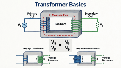
In the two-winding transformers, the primary and secondary windings are electrically isolated from each other and linked only by a magnetic field. However, when electrical isolation is not required, a more efficient and compact alternative exists: the autotransformer.
An autotransformer is a type of electrical transformer that uses a single, continuous winding to serve as both the primary and secondary. By tapping into different points along this single winding, it can step up or step down voltage levels. Because a portion of the power is transferred directly through electrical conduction rather than entirely through magnetic induction, autotransformers are significantly smaller, lighter, and more efficient than their two-winding counterparts for the same power rating.
Autotransformers are ubiquitous in electrical engineering, found in applications ranging from the “Variac” variable transformers on laboratory benches to massive units interconnecting high-voltage power grids, and even in the starting circuits of large industrial motors.
This comprehensive guide will explore the construction, operating principles, mathematical relationships, advantages, limitations, and practical applications of autotransformers.
What is an autotransformer?
An autotransformer is a transformer with a single continuous winding that acts as both the primary and secondary. Unlike conventional transformers, there is no electrical isolation between the input and output. A portion of the power is transferred conductively (directly through the wire) and the rest inductively (via the magnetic field), making it smaller, cheaper, and more efficient than a two-winding transformer.
Construction and Basic Principle
The Single Winding Concept
In a conventional two-winding transformer, there are two distinct coils: the primary (input) and the secondary (output). In an autotransformer, there is only one coil wound on a laminated magnetic core.
This single winding is divided into two distinct electrical sections:
- The Series Winding (or Series Portion): The section of the winding that is in series with the supply or load.
- The Common Winding (or Common Portion): The section of the winding that is shared by both the input and the output circuits.
Step-Down vs. Step-Up Configurations
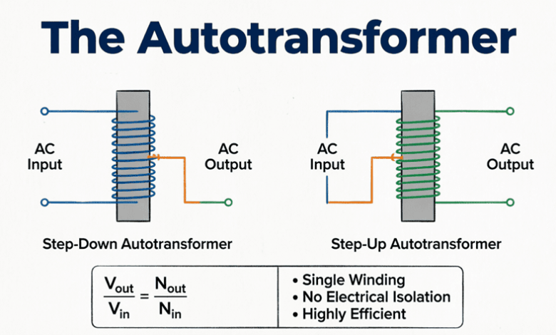
Step-Down Autotransformer:
The full winding is connected across the high-voltage (primary) supply. The load is connected across a portion of the winding.
- The entire winding acts as the primary.
- A tapped portion acts as the secondary.
- Output voltage is lower than input voltage.
Step-Up Autotransformer:
The supply is connected across a portion of the winding. The load is connected across the entire winding.
- A tapped portion acts as the primary.
- The entire winding acts as the secondary.
- Output voltage is higher than input voltage.
How Power is Transferred
This is the most critical concept to understand about autotransformers. In a two-winding transformer, 100% of the power is transferred via magnetic induction. In an autotransformer, power transfer is split into two mechanisms:
- Inductive Power (Transformed Power): The portion of power transferred through the magnetic field from the series winding to the common winding.
- Conductive Power (Conducted Power): The portion of power that flows directly from the input to the output through the electrical connection of the common winding, without being transformed.
Because a large percentage of the power is simply “conducted” straight through, the magnetic core and the copper windings only need to be sized for the much smaller “transformed” portion of the power. This is the secret behind the autotransformer’s compact size.
How is power transferred in an autotransformer?
Power in an autotransformer is transferred in two ways: conductively (directly through the electrical connection of the shared winding) and inductively (via the magnetic field). The core and windings only need to be sized for the inductive (transformed) portion, which is why autotransformers are much smaller than conventional transformers.
Voltage, Current, and Turns Ratio Relationships
The mathematical relationships in an autotransformer are identical to those of a conventional two-winding transformer, provided we look at the total turns and total voltages.
Voltage Ratio
Let:
- $N_1$ = Total number of turns (Primary/High Voltage side)
- $N_2$ = Number of turns in the common/tapped portion (Secondary/Low Voltage side)
- $V_1$ = Primary voltage
- $V_2$ = Secondary voltage
The voltage ratio is:
$\frac{V_1}{V_2} = \frac{N_1}{N_2} = a$
Where $a$ is the turns ratio.
Current Ratio
Assuming an ideal autotransformer (no losses), the input apparent power equals the output apparent power:
$V_1 I_1 = V_2 I_2$
Therefore, the current ratio is the inverse of the turns ratio:
$\frac{I_1}{I_2} = \frac{N_2}{N_1} = \frac{1}{a}$
Current in the Common Winding
One of the most important design parameters is the current flowing through the common winding (the shared section).
In a step-down autotransformer, the current in the common winding ($I_{common}$) is the difference between the secondary current and the primary current:
$I_{common} = I_2 – I_1$
Because $I_2$ is larger than $I_1$ in a step-down configuration, the common winding must be sized to carry this difference. Notice that this current is significantly smaller than the total load current $I_2$, which allows for smaller conductor sizes.
Conducted vs. Transformed Power
To truly appreciate the autotransformer, we must quantify how much power is conducted versus how much is transformed.
The Formulas
For a step-down autotransformer with turns ratio $a = V_1 / V_2$:
Total Apparent Power (Load Power):
$S_{total} = V_2 \times I_2$
Inductive (Transformed) Power:
$S_{ind} = S_{total} \times \left(1 – \frac{1}{a}\right)$
Conductive (Conducted) Power:
$S_{cond} = S_{total} \times \left(\frac{1}{a}\right)$
What This Means in Practice
Let’s look at an extreme example. Suppose we have an autotransformer stepping down 200V to 100V.
- Turns ratio $a = 200 / 100 = 2$.
- Total load power $S_{total} = 10 \text{ kVA}$.
Transformed Power:
$S_{ind} = 10 \text{ kVA} \times (1 – 1/2) = 5 \text{ kVA}$
Conducted Power:
$S_{cond} = 10 \text{ kVA} \times (1/2) = 5 \text{ kVA}$
In this case, only 5 kVA needs to be magnetically transformed. The core and windings only need to be built for a 5 kVA transformer, even though it is delivering 10 kVA to the load!
If the voltage ratio is closer to 1:1 (e.g., 220V to 200V, where $a = 1.1$), the transformed power becomes tiny:
$S_{ind} = S_{total} \times (1 – 1/1.1) = 0.09 \times S_{total}$
Only 9% of the power is transformed! The autotransformer will be roughly 1/11th the size of a conventional two-winding transformer.
Why are autotransformers smaller than conventional transformers?
Autotransformers are smaller because they only need to magnetically transform a fraction of the total load power. The rest of the power is conducted directly from input to output. When the input and output voltages are close in value, the transformed power is very small, allowing for a massive reduction in core size, copper weight, and overall cost.
Advantages of Autotransformers
Autotransformers offer several distinct advantages over conventional two-winding transformers when electrical isolation is not required:
- Smaller Size and Weight: Because the core and windings are only sized for the transformed power, an autotransformer can be significantly smaller and lighter (up to 50-80% smaller for close voltage ratios).
- Lower Cost: Less copper and less core material mean lower manufacturing costs.
- Higher Efficiency: With less copper and a smaller core, both $I^2R$ (copper) losses and core (iron) losses are reduced.
- Better Voltage Regulation: The equivalent resistance and leakage reactance are lower, resulting in less voltage drop under load.
- Lower Excitation Current: Requires less magnetizing current to establish the magnetic flux.
Disadvantages and Limitations
Despite their advantages, autotransformers have critical limitations that restrict their use in certain applications:
- No Electrical Isolation: This is the biggest drawback. The primary and secondary circuits are physically connected. A fault on the high-voltage side (like a ground fault or an open circuit in the common winding) can expose the low-voltage side to full primary voltage, creating a severe safety hazard.
- Higher Short-Circuit Currents: The lower internal impedance means that in the event of a short circuit on the secondary, the fault current will be much higher than with a conventional transformer.
- Harmonic Propagation: Because of the direct electrical connection, harmonics and electrical noise can easily pass from the primary to the secondary.
- Complex Protection: Protecting an autotransformer requires more complex relaying schemes compared to a standard two-winding transformer.
Practical Applications
1. Variable Autotransformers (Variacs)
A Variac (a trademarked name that has become generic) is a variable autotransformer. It features a toroidal (doughnut-shaped) core with a single winding. A carbon brush rides along the exposed surface of the winding, allowing the user to smoothly adjust the output voltage from 0V up to slightly above the input voltage. They are heavily used in laboratories, testing facilities, and audio equipment.
2. Autotransformer Motor Starters
Large induction motors draw 5 to 8 times their full-load current when started directly across the line. To reduce this inrush current, autotransformer starters are used. The motor is initially connected to a reduced voltage tap on the autotransformer (e.g., 50%, 65%, or 80% voltage). Once the motor reaches near-rated speed, the autotransformer is bypassed, and the motor is connected directly to the full line voltage.
3. Interconnecting Power Grids
In high-voltage transmission networks, autotransformers are used to interconnect grids operating at different but relatively close voltage levels (e.g., connecting a 230 kV grid to a 138 kV grid). The massive size and cost savings at these high power levels make autotransformers the standard choice for grid interties.
4. Voltage Regulation (Boosters)
Autotransformers are used as “boosters” on long distribution lines to compensate for voltage drop. By adding a small amount of voltage in series with the line, they maintain the voltage at the far end of the distribution network within acceptable limits.
Practical Examples and Calculations
Example 1: Basic Voltage and Current Calculation
Problem: A step-down autotransformer has a total of 800 turns ($N_1$) and a tap at 600 turns ($N_2$). The primary voltage is 400V. If the load draws 20A at the secondary, calculate the secondary voltage, the primary current, and the current in the common winding.
Solution:
Given:
- $N_1 = 800$ turns
- $N_2 = 600$ turns
- $V_1 = 400\text{V}$
- $I_2 = 20\text{A}$
Calculate Turns Ratio ($a$):
$a = \frac{N_1}{N_2} = \frac{800}{600} = 1.333$
Calculate Secondary Voltage ($V_2$):
$V_2 = \frac{V_1}{a} = \frac{400}{1.333} = 300\text{V}$
Calculate Primary Current ($I_1$):
$I_1 = \frac{I_2}{a} = \frac{20}{1.333} = 15\text{A}$
Calculate Current in Common Winding ($I_{common}$):
$I_{common} = I_2 – I_1 = 20 – 15 = 5\text{A}$
Result: Secondary voltage is 300V, primary current is 15A, and the common winding carries 5A.
Example 2: Conducted vs. Transformed Power
Problem: A 20 kVA, 2400V/2160V autotransformer is supplying a full load. Calculate the amount of power transferred inductively (transformed) and conductively.
Solution:
Given:
- $S_{total} = 20 \text{ kVA}$
- $V_1 = 2400\text{V}$
- $V_2 = 2160\text{V}$
Calculate Turns Ratio ($a$):
$a = \frac{V_1}{V_2} = \frac{2400}{2160} = 1.111$
Calculate Inductive (Transformed) Power:
$S_{ind} = S_{total} \times \left(1 – \frac{1}{a}\right)$
$S_{ind} = 20 \times \left(1 – \frac{1}{1.111}\right)$
$S_{ind} = 20 \times (1 – 0.9) = 20 \times 0.1 = 2 \text{ kVA}$
Calculate Conductive (Conducted) Power:
$S_{cond} = S_{total} \times \left(\frac{1}{a}\right)$
$S_{cond} = 20 \times 0.9 = 18 \text{ kVA}$
(Alternatively: $S_{cond} = S_{total} – S_{ind} = 20 – 2 = 18 \text{ kVA}$)
Result: Only 2 kVA is magnetically transformed, while 18 kVA is conducted directly. The core and windings only need to be designed for a 2 kVA transformer, despite delivering 20 kVA to the load!
Example 3: Converting a Two-Winding Transformer to an Autotransformer
Problem: A standard 10 kVA, 2400/240V two-winding transformer is reconnected as a step-up autotransformer to supply a 2640V load from a 2400V source. Calculate the new kVA rating of the autotransformer.
Solution:
Given:
- Original rating: 10 kVA
- Original Voltages: 2400V (HV), 240V (LV)
Calculate Original Currents:
$I_{HV} = \frac{10,000}{2400} = 4.167\text{A}$
$I_{LV} = \frac{10,000}{240} = 41.67\text{A}$
Autotransformer Connection:
To step up 2400V to 2640V, we connect the 240V winding in series with the 2400V winding.
- Input (Primary): 2400V winding.
- Output (Secondary): 2400V + 240V = 2640V.
Calculate New Apparent Power:
The current in the 240V winding (which is now the series winding) cannot exceed its original rating of 41.67A. This current flows to the load.
$S_{new} = V_{out} \times I_{load}$
$S_{new} = 2640\text{V} \times 41.67\text{A} = 110,000 \text{ VA} = 110 \text{ kVA}$
Result: By reconnecting a 10 kVA two-winding transformer as an autotransformer, its capacity increases to 110 kVA! This massive increase (11 times) occurs because the vast majority of the power is now conducted rather than transformed.
The autotransformer represents a highly efficient, compact, and cost-effective solution for voltage transformation when electrical isolation is not a strict requirement. By utilizing a single continuous winding, it splits the power transfer into conductive and inductive components, allowing the physical hardware to be sized only for the much smaller inductive portion.
Key takeaways from this guide:
- Construction: Uses a single winding with a series portion and a common portion. No electrical isolation exists between input and output.
- Power Transfer: Power is split into Conducted Power (direct electrical transfer) and Transformed Power (magnetic induction).
- Size Advantage: Because it only transforms a fraction of the total power, it is significantly smaller, lighter, and cheaper than a two-winding transformer, especially when the input and output voltages are close.
- Limitations: The lack of isolation poses safety risks, and it allows higher short-circuit currents and harmonic propagation.
- Applications: Ideal for laboratory Variacs, motor starting circuits, grid interconnections, and voltage boosters.
Understanding the autotransformer is essential for any electrical engineer. While the conventional two-winding transformer remains the workhorse for safety and isolation, the autotransformer provides the optimal solution for bulk power transfer and voltage adjustment where isolation can be sacrificed for efficiency and economy.