Audio Transformer
Audio Transformer: Complete Guide to Audio Frequency Transformers
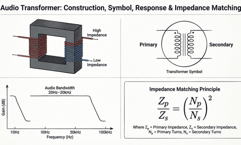
Audio transformers are specialized transformers designed to operate within the audio frequency range (typically 20 Hz to 20 kHz). Unlike power transformers that operate at fixed frequencies (50/60 Hz), audio transformers must maintain consistent performance across a wide frequency spectrum while preserving signal fidelity, minimizing distortion, and providing impedance matching between different stages of audio equipment.
Audio transformers serve critical functions in audio systems:
- Impedance matching between sources and loads
- Signal isolation to prevent ground loops and hum
- Balanced to unbalanced conversion (and vice versa)
- Voltage step-up or step-down for signal levels
- DC isolation between circuit stages
- Common-mode noise rejection in balanced systems
From vintage tube amplifiers to modern professional audio equipment, audio transformers remain essential components for achieving high-quality sound reproduction, noise-free signal transmission, and optimal system performance.
This comprehensive guide will explore audio transformer construction, frequency response characteristics, impedance matching principles, types of audio transformers, and practical applications in audio equipment.
What is an audio transformer?
An audio transformer is a transformer designed to operate in the audio frequency range (20 Hz to 20 kHz). It provides impedance matching, signal isolation, balanced/unbalanced conversion, and DC isolation between audio circuit stages while maintaining flat frequency response and low distortion across the audio spectrum.
Construction and Design Considerations
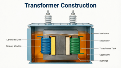
Core Materials
Audio transformers require special core materials to maintain performance across the wide audio frequency range:
1. Silicon Steel (Standard Quality):
- Grain-oriented silicon steel laminations
- Thickness: 0.23mm to 0.35mm
- Suitable for: Budget audio transformers, power applications
- Frequency response: Limited at high frequencies
- Cost: Low
2. Nickel-Iron Alloys (High Quality):
- Permalloy (80% nickel, 20% iron)
- Mu-metal (high permeability)
- Superior magnetic properties
- Better high-frequency response
- Lower core losses
- Cost: High (5-10× silicon steel)
- Used in: Professional audio, high-fidelity equipment
3. Amorphous Metals (Premium):
- Very low core losses
- Excellent frequency response
- Expensive
- Used in: Ultra-high-end audio equipment
Winding Techniques
Interleaved Windings:
- Primary and secondary windings are interleaved (alternating layers)
- Reduces leakage inductance
- Improves high-frequency response
- Better coupling between windings
- More complex construction
Layer Winding:
- Primary wound first, then secondary
- Simpler construction
- Higher leakage inductance
- Poorer high-frequency response
- Lower cost
Bifilar Winding:
- Two wires wound simultaneously
- Very tight coupling
- Used for: Impedance matching, balanced outputs
- Excellent phase matching
Core Configurations
1. E-I Core (Most Common):
- Laminations in E and I shapes
- Cost-effective
- Good performance
- Easy to manufacture
- Standard for most audio transformers
2. C-Core (Toroidal):
- Continuous grain-oriented steel
- Lower magnetic losses
- Better efficiency
- Lower stray magnetic field
- More expensive
- Used in: High-end equipment
3. Toroidal Core:
- Circular core shape
- Minimal magnetic leakage
- Compact size
- Efficient
- Difficult to wind
- Used in: Premium audio equipment
Why do audio transformers use special core materials?
Audio transformers must operate from 20 Hz to 20 kHz, a much wider range than power transformers. Special core materials like nickel-iron alloys (permalloy) provide better permeability and lower losses across this wide frequency range, ensuring flat frequency response and low distortion.
Frequency Response Characteristics
Low-Frequency Response
Low-frequency response is determined by:
1. Primary Inductance (L_p):
- Higher inductance = better low-frequency response
- $f_{low} = \frac{R}{2\pi L_p}$
- Where R is the source/load impedance
- To extend low-frequency response:
- Increase number of turns
- Use higher permeability core
- Increase core cross-sectional area
2. Core Saturation:
- At low frequencies, flux density increases
- Core can saturate, causing distortion
- Larger core cross-section prevents saturation
- Trade-off: Size vs. low-frequency performance
Typical Low-Frequency Limits:
- Budget transformers: 50-100 Hz (-3 dB)
- Good quality: 20-30 Hz (-3 dB)
- High-end: 10-20 Hz (-3 dB)
- Premium: Below 10 Hz (-3 dB)
High-Frequency Response
High-frequency response is limited by:
1. Leakage Inductance (L_leak):
- Magnetic flux that doesn’t link both windings
- Forms low-pass filter with load
- $f_{high} = \frac{R}{2\pi L_{leak}}$
- Reduced by:
- Interleaved windings
- Tight coupling
- Bifilar winding
2. Winding Capacitance (C_w):
- Capacitance between winding turns
- Forms low-pass filter
- Reduced by:
- Sectional winding
- Proper insulation
- Increased spacing
3. Core Losses:
- Eddy current and hysteresis losses increase with frequency
- Cause high-frequency roll-off
- Minimized by:
- Thin laminations
- High-resistivity core material
Typical High-Frequency Limits:
- Budget transformers: 10-15 kHz (-3 dB)
- Good quality: 20-30 kHz (-3 dB)
- High-end: 50-100 kHz (-3 dB)
- Premium: Above 100 kHz (-3 dB)
Midband Flatness
In the midband (typically 100 Hz to 10 kHz), the transformer should have:
- Flat frequency response (±0.5 dB or better)
- Low phase shift
- Minimal distortion
- Consistent impedance
Factors Affecting Midband Performance:
- Winding resistance
- Core quality
- Coupling coefficient
- Construction quality
Impedance Matching
The Importance of Impedance Matching
Impedance matching is one of the primary functions of audio transformers. Proper impedance matching ensures:
Maximum Power Transfer:
- When source impedance equals load impedance
- Maximum power is transferred
- Critical for: Tube amplifiers, microphones
Optimal Signal Transfer:
- Prevents signal reflection
- Minimizes frequency response anomalies
- Reduces distortion
Noise Reduction:
- Proper matching reduces susceptibility to noise
- Improves signal-to-noise ratio
Impedance Ratio
The impedance ratio of a transformer is the square of the turns ratio:
$\frac{Z_p}{Z_s} = \left(\frac{N_p}{N_s}\right)^2 = n^2$
Where:
- $Z_p$ = Primary impedance
- $Z_s$ = Secondary impedance
- $N_p$ = Primary turns
- $N_s$ = Secondary turns
- $n$ = Turns ratio
Example:
To match a 10,000Ω tube output to an 8Ω speaker:
Impedance ratio: $\frac{10,000}{8} = 1,250$
Turns ratio: $n = \sqrt{1,250} = 35.36:1$
The transformer needs approximately 35:1 turns ratio.
Common Impedance Matching Applications
1. Tube Amplifier Output:
- Tube plate impedance: 2,000Ω to 10,000Ω
- Speaker impedance: 4Ω, 8Ω, or 16Ω
- Typical impedance ratio: 500:1 to 2,500:1
- Turns ratio: 22:1 to 50:1
2. Microphone to Preamp:
- Dynamic microphone: 150Ω to 600Ω
- Preamp input: 1,000Ω to 10,000Ω
- Typical ratio: 1:5 to 1:15
3. Line Matching:
- Professional line: 600Ω
- Consumer line: 10,000Ω
- Ratio: 1:16.7 (or 4:1 turns ratio)
Impedance Bridging vs. Matching
Impedance Matching:
- Source impedance = Load impedance
- Maximum power transfer
- Used in: Tube amplifiers, microphones
Impedance Bridging:
- Load impedance >> Source impedance (typically 10:1)
- Maximum voltage transfer
- Minimal loading effect
- Used in: Modern solid-state equipment, line-level connections
How do you calculate the turns ratio for impedance matching?
The turns ratio is the square root of the impedance ratio: n = √(Z_p/Z_s). For example, to match 10,000Ω to 8Ω, the turns ratio is √(10,000/8) = √1,250 = 35.36:1.
Types of Audio Transformers
1. Input Transformers
Purpose:
- Interface between source and amplifier
- Provide impedance matching
- Balanced to unbalanced conversion
- Common-mode noise rejection
Characteristics:
- Primary: Balanced (600Ω typical)
- Secondary: Unbalanced or balanced
- High common-mode rejection ratio (CMRR)
- Low distortion
- Wide frequency response
Applications:
- Microphone preamplifiers
- Professional audio interfaces
- Mixing consoles
- DI (Direct Injection) boxes
2. Output Transformers
Purpose:
- Interface between amplifier and load
- Impedance matching (especially for tube amplifiers)
- DC isolation
- Balanced or unbalanced output
Characteristics:
- Handle significant power
- Low distortion at high levels
- Wide frequency response
- Proper impedance ratio
Applications:
- Tube amplifier outputs
- Power amplifiers
- Speaker crossovers
- Line drivers
3. Interstage Transformers
Purpose:
- Couple between amplifier stages
- DC isolation
- Impedance matching between stages
- Phase splitting (push-pull amplifiers)
Characteristics:
- Low signal level
- Wide frequency response
- Low distortion
- Precise phase relationships
Applications:
- Tube amplifier interstage coupling
- Phase splitters
- Driver stages
4. Line Transformers
Purpose:
- Interface between equipment
- Balanced/unbalanced conversion
- Ground loop isolation
- Impedance matching for long lines
Characteristics:
- 600Ω:600Ω or 600Ω:10kΩ ratios
- Good common-mode rejection
- Wide frequency response
- Low insertion loss
Applications:
- Professional audio connections
- Long cable runs
- Ground loop elimination
- Studio equipment interconnection
5. Microphone Transformers
Purpose:
- Match microphone to preamp
- Balanced output
- Impedance transformation
- Common-mode rejection
Characteristics:
- Low distortion
- Wide frequency response (20 Hz to 20 kHz)
- Low noise
- High CMRR (>60 dB)
Applications:
- Dynamic microphones
- Ribbon microphones
- Vintage microphone restoration
6. Speaker Matching Transformers
Purpose:
- Match amplifier to speaker
- Multiple impedance taps
- Constant voltage distribution (70V/100V systems)
Characteristics:
- Multiple secondary taps (4Ω, 8Ω, 16Ω)
- Handle high power
- Low insertion loss
- Wide frequency response
Applications:
- Tube amplifiers
- PA systems
- Distributed speaker systems
- Constant voltage systems
Practical Applications
1. Tube Amplifier Output Stage
Configuration:
- Primary: Connected to tube plates
- Secondary: Connected to speaker
- Impedance ratio: Typically 500:1 to 2,500:1
- Power rating: 5W to 100W+
Critical Parameters:
- Frequency response: 20 Hz to 20 kHz (±1 dB)
- Distortion: <1% at rated power
- Phase response: Linear
- Insertion loss: <0.5 dB
2. Balanced Line Driver
Configuration:
- Primary: Unbalanced input
- Secondary: Balanced output (center-tapped)
- Impedance ratio: 1:1 or 1:4
- CMRR: >60 dB
Benefits:
- Rejects common-mode noise
- Allows long cable runs
- Eliminates ground loops
- Professional audio standard
3. Direct Injection (DI) Box
Configuration:
- High-impedance input (guitar, keyboard)
- Low-impedance balanced output
- Impedance ratio: Typically 10:1 to 20:1
- Pad switch for level adjustment
Applications:
- Connect instruments to mixing console
- Long cable runs to stage
- Ground loop isolation
- Impedance matching
4. Ground Loop Isolator
Configuration:
- 1:1 ratio transformer
- Balanced input and output
- High isolation voltage
- Wide frequency response
Purpose:
- Eliminate 60 Hz hum from ground loops
- Break ground connection while passing audio
- Maintain signal integrity
- Common in professional audio
5. Phono Stage Input
Configuration:
- Match phono cartridge to preamp
- Impedance: 47kΩ load for MM cartridges
- Low noise
- Wide frequency response
Applications:
- Vinyl record playback
- Moving magnet cartridges
- Moving coil cartridges (with step-up transformer)
Practical Examples and Calculations
Example 1: Output Transformer Design
Problem: Design an output transformer for a tube amplifier with the following specifications:
- Tube plate impedance: 5,000Ω
- Speaker impedance: 8Ω
- Power rating: 50W
- Frequency response: 20 Hz to 20 kHz (±1 dB)
Calculate:
- Impedance ratio
- Turns ratio
- Primary inductance required for 20 Hz response
Solution:
1. Impedance Ratio:
$\frac{Z_p}{Z_s} = \frac{5,000}{8} = 625$
2. Turns Ratio:
$n = \sqrt{625} = 25:1$
3. Primary Inductance:
For -3 dB at 20 Hz:
$f_{low} = \frac{R}{2\pi L_p}$
Where R is the reflected load impedance:
$R = Z_p = 5,000\Omega$
For -1 dB (better quality):
$L_p = \frac{R}{2\pi f_{low}} = \frac{5,000}{2\pi \times 20} = \frac{5,000}{125.66} = 39.8 \text{ H}$
For -3 dB point:
$L_p = \frac{5,000}{2\pi \times 20} \times 0.5 = 19.9 \text{ H}$
Result:
- Impedance ratio: 625:1
- Turns ratio: 25:1
- Primary inductance: 20-40 H (depending on low-frequency specification)
Example 2: Microphone Transformer Matching
Problem: A dynamic microphone has an output impedance of 200Ω. The preamp input impedance is 2,000Ω. Calculate the transformer turns ratio for impedance matching.
Solution:
Impedance Ratio:
$\frac{Z_p}{Z_s} = \frac{200}{2,000} = 0.1$
Turns Ratio:
$n = \sqrt{0.1} = 0.316:1$
Or inverted:
$n = \frac{1}{0.316} = 3.16:1$ (step-up)
Result: Use a transformer with approximately 1:3.16 turns ratio (primary:secondary) to match 200Ω microphone to 2,000Ω preamp input.
Example 3: Frequency Response Calculation
Problem: An audio transformer has a primary inductance of 10 H and a leakage inductance of 5 mH. The source/load impedance is 600Ω. Calculate the -3 dB low and high frequency limits.
Solution:
Low-Frequency Limit:
$f_{low} = \frac{R}{2\pi L_p} = \frac{600}{2\pi \times 10} = \frac{600}{62.83} = 9.55 \text{ Hz}$
High-Frequency Limit:
$f_{high} = \frac{R}{2\pi L_{leak}} = \frac{600}{2\pi \times 0.005} = \frac{600}{0.0314} = 19,108 \text{ Hz} \approx 19.1 \text{ kHz}$
Result:
- Low-frequency -3 dB point: 9.55 Hz (excellent)
- High-frequency -3 dB point: 19.1 kHz (good, covers audio range)
- Bandwidth: 9.55 Hz to 19.1 kHz
Audio transformers are essential components in professional and high-fidelity audio systems, providing critical functions including impedance matching, signal isolation, balanced/unbalanced conversion, and DC isolation. Their design requires careful consideration of frequency response, core materials, winding techniques, and impedance ratios.
Key takeaways from this guide:
- Construction:
- Core materials: Silicon steel (budget), nickel-iron (high-end), amorphous (premium)
- Winding techniques: Interleaved for better high-frequency response
- Core configurations: E-I (common), C-core, toroidal (premium)
- Frequency Response:
- Low-frequency: Determined by primary inductance
- High-frequency: Limited by leakage inductance and winding capacitance
- Midband: Should be flat (±0.5 dB) from 100 Hz to 10 kHz
- Impedance Matching:
- Turns ratio = (impedance ratio)
- Critical for tube amplifiers and microphones
- Ensures maximum power transfer
- Types:
- Input transformers: Microphone preamps, DI boxes
- Output transformers: Tube amplifiers, line drivers
- Interstage transformers: Coupling between stages
- Line transformers: Balanced connections
- Applications:
- Tube amplifier outputs
- Balanced line drivers
- Ground loop isolation
- Microphone matching
- Speaker systems
- Design Trade-offs:
- Size vs. low-frequency response
- Cost vs. performance
- Leakage inductance vs. high-frequency response
- Core saturation vs. power handling
Mastering audio transformer principles enables engineers to design high-quality audio equipment, troubleshoot audio systems, and achieve optimal sound reproduction. Whether designing a tube amplifier, building a microphone preamp, or installing professional audio systems, understanding audio transformers is essential for achieving exceptional audio performance.