Conversion of Flip-flops
Conversion of Flip-flops: Complete Guide to SR, JK, D, and T Conversions
Introduction to Flip-flop Conversion
In digital electronics design, you often encounter situations where a specific type of flip-flop is required for a particular application, but only a different type is available. Flip-flop conversion is the process of converting one type of flip-flop into another by adding external combinational logic circuits.
For example:
- You might need a D flip-flop for data storage, but only have JK flip-flops available
- A design requires a T flip-flop for toggling, but you only have SR flip-flops
- You need to convert an SR flip-flop to a JK flip-flop to eliminate the forbidden state
Understanding flip-flop conversion is essential for:
- Flexible digital design
- Component substitution
- Optimizing circuit implementations
- Understanding the relationships between different flip-flop types
- Custom circuit design when specific ICs are unavailable
This comprehensive guide will explore the systematic methods for converting between all major flip-flop types (SR, JK, D, and T), complete with excitation tables, Karnaugh maps, logic diagrams, and practical examples.
What is flip-flop conversion?
Flip-flop conversion is the process of converting one type of flip-flop (e.g., SR, JK, D, or T) into another type by adding external combinational logic gates. This is done using excitation tables and Boolean algebra to determine the required logic that makes the available flip-flop behave like the desired flip-flop.
Understanding Flip-flop Characteristics
Before diving into conversion techniques, it’s essential to understand the fundamental characteristics of each flip-flop type.
SR Flip-flop (Set-Reset)
- Inputs: S (Set), R (Reset)
- Operation:
- S=1, R=0 → Q=1 (Set)
- S=0, R=1 → Q=0 (Reset)
- S=0, R=0 → Q holds (No change)
- S=1, R=1 → Invalid/Forbidden state
- Characteristic: Simple but has a forbidden state
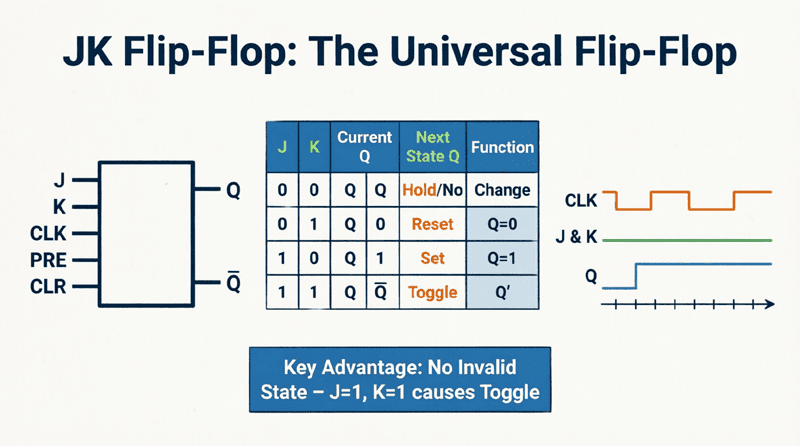
JK Flip-flop (Jack Kilby)
- Inputs: J, K
- Operation:
- J=0, K=0 → Q holds (No change)
- J=0, K=1 → Q=0 (Reset)
- J=1, K=0 → Q=1 (Set)
- J=1, K=1 → Q toggles
- Characteristic: Universal flip-flop, no forbidden state
D Flip-flop (Data/Delay)
- Inputs: D (Data)
- Operation:
- D=0 → Q=0 (Reset)
- D=1 → Q=1 (Set)
- Characteristic: Simplest, output follows input on clock edge
T Flip-flop (Toggle)
- Inputs: T (Toggle)
- Operation:
- T=0 → Q holds (No change)
- T=1 → Q toggles
- Characteristic: Simple toggling, useful for counters
What are the four main types of flip-flops?
The four main types are: SR (Set-Reset, has forbidden state), JK (universal, no forbidden state, can toggle), D (Data, simplest, output follows input), and T (Toggle, toggles when T=1). Each has unique characteristics that make it suitable for different applications.
The Conversion Process: Step-by-Step Methodology
Converting one flip-flop type to another follows a systematic approach:
Step 1: Define the Conversion Goal
Identify which flip-flop you have (available) and which one you need (desired).
Example: Convert SR flip-flop to JK flip-flop
- Available: SR flip-flop
- Desired: JK flip-flop behavior
Step 2: Create the Excitation Table
An excitation table shows what inputs are required to transition from the current state (Qn) to the next state (Qn+1).
For the available flip-flop, create a table showing:
- Current state (Qn)
- Next state (Qn+1)
- Required inputs for the available flip-flop
Step 3: Create the Truth Table
Create a truth table that includes:
- Inputs of the desired flip-flop
- Current state (Qn)
- Next state (Qn+1)
- Required inputs for the available flip-flop (from Step 2)
Step 4: Use Karnaugh Maps (K-maps)
Use K-maps to simplify the Boolean expressions for the available flip-flop’s inputs in terms of the desired flip-flop’s inputs and the current state.
Step 5: Design the Combinational Logic
Based on the simplified Boolean expressions, design the combinational logic circuit using logic gates (AND, OR, NOT, etc.).
Step 6: Connect the Circuit
Connect the combinational logic circuit to the available flip-flop to create the converted flip-flop.
Common Flip-flop Conversions
Let’s explore the most common flip-flop conversions with detailed examples.
1. SR to JK Flip-flop Conversion
Goal: Make an SR flip-flop behave like a JK flip-flop.
Step 1: JK Flip-flop Truth Table
| J | K | Qn | Qn+1 |
|---|---|---|---|
| 0 | 0 | 0 | 0 |
| 0 | 0 | 1 | 1 |
| 0 | 1 | 0 | 0 |
| 0 | 1 | 1 | 0 |
| 1 | 0 | 0 | 1 |
| 1 | 0 | 1 | 1 |
| 1 | 1 | 0 | 1 |
| 1 | 1 | 1 | 0 |
Step 2: SR Flip-flop Excitation Table
| Qn | Qn+1 | S | R |
|---|---|---|---|
| 0 | 0 | 0 | X |
| 0 | 1 | 1 | 0 |
| 1 | 0 | 0 | 1 |
| 1 | 1 | X | 0 |
(X = Don’t care)
Step 3: Combined Truth Table
| J | K | Qn | Qn+1 | S | R |
|---|---|---|---|---|---|
| 0 | 0 | 0 | 0 | 0 | X |
| 0 | 0 | 1 | 1 | X | 0 |
| 0 | 1 | 0 | 0 | 0 | X |
| 0 | 1 | 1 | 0 | 0 | 1 |
| 1 | 0 | 0 | 1 | 1 | 0 |
| 1 | 0 | 1 | 1 | X | 0 |
| 1 | 1 | 0 | 1 | 1 | 0 |
| 1 | 1 | 1 | 0 | 0 | 1 |
Step 4: K-maps for S and R
K-map for S:
     JK
     00  01  11  10
Qn 0 | 0 | 0 | 1 | 1 |
   1 | X | 0 | 0 | X |
Simplified: S = J · Qn’
K-map for R:
     JK
     00  01  11  10
Qn 0 | X | X | 0 | 0 |
   1 | 0 | 1 | 1 | 0 |
Simplified: R = K · Qn
Step 5: Circuit Implementation
- Connect J and Qn’ (Qn inverted) to an AND gate → S input
- Connect K and Qn to an AND gate → R input
How do you convert an SR flip-flop to a JK flip-flop?
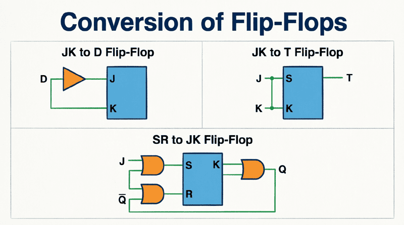
To convert SR to JK: Connect S = J · Qn’ and R = K · Qn. This requires two AND gates: one AND gate takes J and Qn’ (inverted Q) as inputs for S, and another AND gate takes K and Q as inputs for R.
2. JK to D Flip-flop Conversion
Goal: Make a JK flip-flop behave like a D flip-flop.
Step 1: D Flip-flop Truth Table
| D | Qn | Qn+1 |
|---|---|---|
| 0 | 0 | 0 |
| 0 | 1 | 0 |
| 1 | 0 | 1 |
| 1 | 1 | 1 |
Step 2: JK Flip-flop Excitation Table
| Qn | Qn+1 | J | K |
|---|---|---|---|
| 0 | 0 | 0 | X |
| 0 | 1 | 1 | X |
| 1 | 0 | X | 1 |
| 1 | 1 | X | 0 |
Step 3: Combined Truth Table
| D | Qn | Qn+1 | J | K |
|---|---|---|---|---|
| 0 | 0 | 0 | 0 | X |
| 0 | 1 | 0 | X | 1 |
| 1 | 0 | 1 | 1 | X |
| 1 | 1 | 1 | X | 0 |
Step 4: K-maps for J and K
K-map for J:
     D
     0   1
Qn 0 | 0 | 1 |
   1 | X | X |
Simplified: J = D
K-map for K:
     D
     0   1
Qn 0 | X | X |
   1 | 1 | 0 |
Simplified: K = D’
Step 5: Circuit Implementation
- Connect D directly to J input
- Connect D through an inverter (NOT gate) to K input
This is a very simple conversion!
3. JK to T Flip-flop Conversion
Goal: Make a JK flip-flop behave like a T flip-flop.
Step 1: T Flip-flop Truth Table
| T | Qn | Qn+1 |
|---|---|---|
| 0 | 0 | 0 |
| 0 | 1 | 1 |
| 1 | 0 | 1 |
| 1 | 1 | 0 |
Step 2: JK Flip-flop Excitation Table
| Qn | Qn+1 | J | K |
|---|---|---|---|
| 0 | 0 | 0 | X |
| 0 | 1 | 1 | X |
| 1 | 0 | X | 1 |
| 1 | 1 | X | 0 |
Step 3: Combined Truth Table
| T | Qn | Qn+1 | J | K |
|---|---|---|---|---|
| 0 | 0 | 0 | 0 | X |
| 0 | 1 | 1 | X | 0 |
| 1 | 0 | 1 | 1 | X |
| 1 | 1 | 0 | X | 1 |
Step 4: K-maps for J and K
K-map for J:
     T
     0   1
Qn 0 | 0 | 1 |
   1 | X | X |
Simplified: J = T
K-map for K:
     T
     0   1
Qn 0 | X | X |
   1 | 0 | 1 |
Simplified: K = T
Step 5: Circuit Implementation
- Connect T to both J and K inputs
This is the simplest conversion! When J=K=T, the JK flip-flop toggles when T=1 and holds when T=0, exactly like a T flip-flop.
4. D to T Flip-flop Conversion
Goal: Make a D flip-flop behave like a T flip-flop.
Step 1: T Flip-flop Truth Table
| T | Qn | Qn+1 |
|---|---|---|
| 0 | 0 | 0 |
| 0 | 1 | 1 |
| 1 | 0 | 1 |
| 1 | 1 | 0 |
Step 2: D Flip-flop Excitation Table
| Qn | Qn+1 | D |
|---|---|---|
| 0 | 0 | 0 |
| 0 | 1 | 1 |
| 1 | 0 | 0 |
| 1 | 1 | 1 |
Step 3: Combined Truth Table
| T | Qn | Qn+1 | D |
|---|---|---|---|
| 0 | 0 | 0 | 0 |
| 0 | 1 | 1 | 1 |
| 1 | 0 | 1 | 1 |
| 1 | 1 | 0 | 0 |
Step 4: K-map for D
     T
     0   1
Qn 0 | 0 | 1 |
   1 | 1 | 0 |
This is an XOR pattern!
Simplified: D = T ⊕ Qn (T XOR Qn)
Step 5: Circuit Implementation
- Connect T and Qn to an XOR gate
- Connect the XOR output to D input
5. SR to D Flip-flop Conversion
Goal: Make an SR flip-flop behave like a D flip-flop.
Step 1: D Flip-flop Truth Table
| D | Qn | Qn+1 |
|---|---|---|
| 0 | 0 | 0 |
| 0 | 1 | 0 |
| 1 | 0 | 1 |
| 1 | 1 | 1 |
Step 2: SR Flip-flop Excitation Table
| Qn | Qn+1 | S | R |
|---|---|---|---|
| 0 | 0 | 0 | X |
| 0 | 1 | 1 | 0 |
| 1 | 0 | 0 | 1 |
| 1 | 1 | X | 0 |
Step 3: Combined Truth Table
| D | Qn | Qn+1 | S | R |
|---|---|---|---|---|
| 0 | 0 | 0 | 0 | X |
| 0 | 1 | 0 | 0 | 1 |
| 1 | 0 | 1 | 1 | 0 |
| 1 | 1 | 1 | X | 0 |
Step 4: K-maps for S and R
K-map for S:
     D
     0   1
Qn 0 | 0 | 1 |
   1 | 0 | X |
Simplified: S = D · Qn’
K-map for R:
     D
     0   1
Qn 0 | X | 0 |
   1 | 1 | 0 |
Simplified: R = D’ · Qn
Step 5: Circuit Implementation
- S = D · Qn’ (AND gate with D and Qn inverted)
- R = D’ · Qn (AND gate with D inverted and Qn)
This ensures S and R are never both 1, avoiding the forbidden state.
Summary of Conversion Equations
Here’s a quick reference table for common flip-flop conversions:
| Conversion | Input Equations |
|---|---|
| SR → JK | S = J·Qn’, R = K·Qn |
| JK → D | J = D, K = D’ |
| JK → T | J = T, K = T |
| D → T | D = T ⊕ Qn |
| SR → D | S = D·Qn’, R = D’·Qn |
| D → JK | D = J·Qn’ + K’·Qn |
| T → JK | J = T, K = T |
| T → D | D = T ⊕ Qn |
Practical Applications of Flip-flop Conversion
1. Component Substitution
When a specific flip-flop IC is unavailable, you can convert an available type to meet your design requirements.
2. Design Optimization
Sometimes converting flip-flops can reduce the overall gate count or simplify the circuit.
3. Educational Purposes
Understanding conversions helps students grasp the relationships between different flip-flop types and their underlying principles.
4. Custom Circuit Design
In FPGA or ASIC design, you might have access to only certain types of flip-flops and need to convert them for specific functionality.
5. Legacy System Maintenance
When maintaining older systems, you might need to replace components with modern equivalents that require conversion.
Flip-flop conversion is a fundamental skill in digital electronics that enables designers to flexibly implement sequential logic circuits using available components. By understanding the excitation tables, truth tables, and K-map simplification techniques, you can convert between any flip-flop types.
Key takeaways from this guide include:
- Systematic Approach: Follow the 6-step methodology: define goal, create excitation table, create truth table, use K-maps, design logic, and connect circuit.
- Common Conversions:
- JK to D: J=D, K=D’ (simplest)
- JK to T: J=T, K=T (simplest)
- D to T: D=T⊕Qn (XOR gate)
- SR to JK: S=J·Qn’, R=K·Qn
- Excitation Tables: Essential tools that show what inputs are needed to achieve desired state transitions.
- K-maps: Powerful simplification tools that minimize the combinational logic required for conversion.
- Practical Value: Conversions enable component substitution, design optimization, and flexible circuit implementation.
Mastering flip-flop conversion techniques empowers you to design more flexible, efficient, and adaptable digital systems. Whether you’re working with discrete logic gates, FPGAs, or ASICs, these conversion skills are invaluable tools in your digital design toolkit.