Inductive Reactance
Inductive Reactance: Complete Guide to AC Opposition and Frequency Response
Introduction to Inductive Reactance
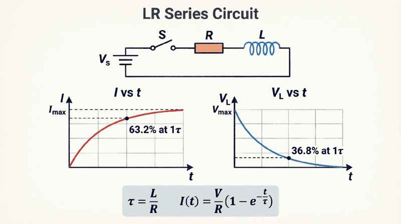
Inductors ability to store energy in a magnetic field, and its transient behavior in DC circuits. However, the true magic of the inductor is revealed when it is placed in an Alternating Current (AC) circuit.
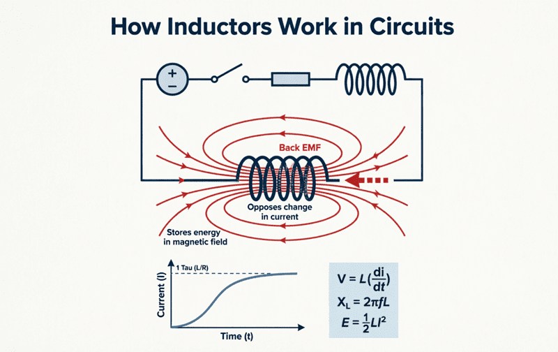
In a DC circuit, once the current stabilizes, an ideal inductor acts as a short circuit, offering zero opposition to the steady flow of electrons. But in an AC circuit, where the current is constantly changing direction and magnitude, the inductor continuously generates a back electromotive force (EMF) to oppose those changes. This continuous, frequency-dependent opposition to alternating current is known as Inductive Reactance, denoted by the symbol $X_L$.
Unlike standard resistance, which dissipates energy as heat, inductive reactance temporarily stores and releases energy, causing a phase shift between voltage and current. Understanding $X_L$ is absolutely critical for designing filters, tuning circuits, managing power quality, and selecting the right components for high-frequency or power-line applications. This comprehensive guide will break down the physics, mathematics, and practical applications of inductive reactance.
What is Inductive Reactance?
Inductive reactance ($X_L$) is the opposition that an inductor presents to the flow of alternating current (AC). Unlike DC resistance, it does not dissipate energy as heat but instead stores it in a magnetic field. It is measured in Ohms ($\Omega$) and increases linearly with both the frequency of the AC signal and the inductance of the coil.
The Physics of Inductive Reactance
To understand why an inductor opposes AC, we must revisit Faraday’s Law of Induction and Lenz’s Law.
When an alternating current flows through a coil, the constantly changing current produces a constantly expanding and collapsing magnetic field. According to Faraday’s Law, this changing magnetic flux induces a voltage across the coil. According to Lenz’s Law, the polarity of this induced voltage (the back EMF) is always in a direction that opposes the change in current that created it.
Because the AC current is always changing, the back EMF is always present. The faster the current changes, the stronger the back EMF, and the greater the opposition to the current flow.
Therefore, if you increase the frequency of the AC source, the current changes more rapidly. This induces a larger back EMF, which in turn restricts the current more effectively. This is why inductive reactance is directly tied to frequency.
The Formula for Inductive Reactance
The magnitude of inductive reactance is determined by a simple, elegant mathematical formula:
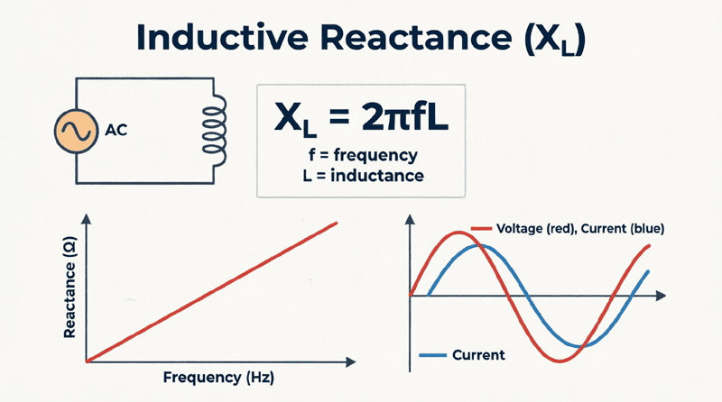
$X_L = 2\pi f L$
Alternatively, using angular frequency ($\omega = 2\pi f$):
$X_L = \omega L$
Where:
- $X_L$ = Inductive reactance in Ohms ($\Omega$)
- $\pi$ = Pi (approximately 3.14159)
- $f$ = Frequency of the AC supply in Hertz (Hz)
- $L$ = Inductance of the coil in Henrys (H)
- $\omega$ = Angular frequency in radians per second (rad/s)
Breaking Down the Variables
- Inductance ($L$): A coil with more turns or a higher-permeability core will generate a stronger magnetic field for a given current, resulting in a stronger back EMF and higher reactance.
- Frequency ($f$): Higher frequency means the current changes direction more times per second. This increases the rate of change ($di/dt$), inducing a higher back EMF and thus higher reactance.
What is the formula for Inductive Reactance?
The formula for inductive reactance is $X_L = 2\pi f L$, where $f$ is the frequency in Hertz and $L$ is the inductance in Henrys. This shows that reactance is directly proportional to both frequency and inductance.
Frequency Response: The “Choke” Effect
The direct proportionality between $X_L$ and frequency gives the inductor its most useful characteristic: it acts as a frequency-dependent resistor.
At DC (Frequency = 0 Hz)
If we plug $f = 0$ into the formula, we get $X_L = 0 \Omega$. In a DC circuit, after the initial transient period, the inductor offers zero reactance and acts as a short circuit (limited only by the tiny DC resistance of the wire).
At Low Frequencies
At low AC frequencies (like 50 Hz or 60 Hz mains power), the reactance is relatively low. Large currents can flow through the inductor with minimal opposition.
At High Frequencies
As the frequency climbs into the kilohertz (kHz) or megahertz (MHz) range, the reactance becomes enormous. The inductor effectively blocks the high-frequency AC, acting almost like an open circuit.
Because of this behavior, inductors are frequently used as chokes. A “choke” is an inductor specifically designed to “choke off” or block high-frequency AC noise while allowing DC or low-frequency signals to pass through unimpeded.
Phase Relationship in a Pure Inductor
While resistance opposes current uniformly, inductive reactance introduces a time delay, or phase shift, between the voltage and the current.
In a purely inductive AC circuit (where resistance is negligible), the back EMF is maximum when the current is changing fastest (at the zero-crossing points) and zero when the current is momentarily constant (at the peak values).
This physical reality results in a strict rule: In a pure inductor, the voltage leads the current by exactly 90 degrees (or conversely, the current lags the voltage by 90 degrees).
This 90-degree phase shift is crucial for power calculations. Because the voltage and current peaks do not align, a pure inductor consumes zero real power (Watts). It only consumes reactive power (VARs), continuously exchanging energy with the source without dissipating it.
Practical Calculation Examples
Let’s apply the formula to real-world scenarios to see how frequency and inductance affect reactance.
Example 1: Standard Mains Frequency
Problem: Calculate the inductive reactance of a 0.5 Henry inductor connected to a standard 60 Hz AC power supply.
Solution:
Given: $L = 0.5 \text{ H}$, $f = 60 \text{ Hz}$
$X_L = 2 \times \pi \times 60 \times 0.5$
$X_L = 2 \times 3.14159 \times 30$
$X_L \approx 188.5 \Omega$
Example 2: The Effect of Doubling Frequency
Problem: Using the same 0.5 H inductor from Example 1, what happens to the reactance if the frequency is doubled to 120 Hz?
Solution:
Given: $L = 0.5 \text{ H}$, $f = 120 \text{ Hz}$
$X_L = 2 \times \pi \times 120 \times 0.5$
$X_L = 2 \times 3.14159 \times 60$
$X_L \approx 377.0 \Omega$
Observation: Doubling the frequency exactly doubled the inductive reactance. This linear relationship is a hallmark of ideal inductors.
Example 3: Calculating Inductance from Reactance
Problem: An RF engineer needs an inductor that provides $500 \Omega$ of reactance at a frequency of 1 MHz ($1,000,000 \text{ Hz}$). What inductance value is required?
Solution:
Rearrange the formula to solve for $L$:
$L = \frac{X_L}{2\pi f}$
$L = \frac{500}{2 \times 3.14159 \times 1,000,000}$
$L = \frac{500}{6,283,180}$
$L \approx 0.0000796 \text{ H} = 79.6 \text{ \mu H}$ (microhenrys)
Combining Inductive Reactances
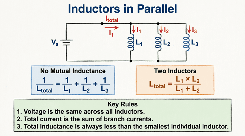
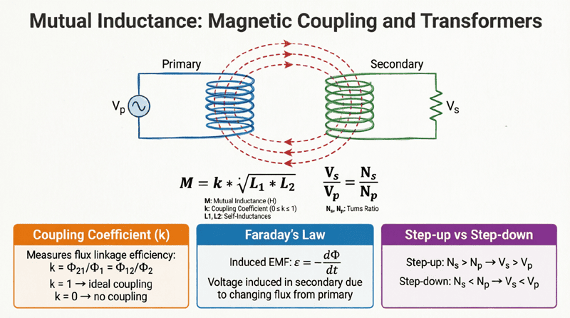
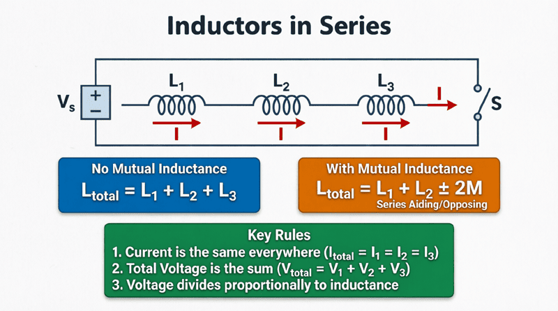
Just like standard resistors, inductive reactances can be combined in series and parallel circuits. However, you can only add reactances directly if they are not magnetically coupled (no mutual inductance).
Reactance in Series
When uncoupled inductors are connected in series, their reactances simply add together:
$X_{L(total)} = X_{L1} + X_{L2} + X_{L3} + …$
Reactance in Parallel
When uncoupled inductors are connected in parallel, their total reactance is calculated using the reciprocal formula:
$\frac{1}{X_{L(total)}} = \frac{1}{X_{L1}} + \frac{1}{X_{L2}} + \frac{1}{X_{L3}} + …$
For exactly two inductors in parallel, the product-over-sum rule applies:
$X_{L(total)} = \frac{X_{L1} \times X_{L2}}{X_{L1} + X_{L2}}$
How do you combine inductive reactances?
Inductive reactances combine exactly like resistors. In series, you add them directly ($X_{total} = X_1 + X_2$). In parallel, you use the reciprocal formula ($1/X_{total} = 1/X_1 + 1/X_2$).
Practical Applications of Inductive Reactance
The frequency-dependent nature of $X_L$ makes inductors indispensable in modern electronics and power systems.
1. RF Chokes (Radio Frequency Chokes)
In radio and audio circuits, you often need to pass DC power to an amplifier while blocking high-frequency AC signals from traveling back up the power line. An RF choke (an inductor with high $X_L$ at radio frequencies but low DC resistance) is placed in series with the power line. It allows the DC to pass freely but presents a massive wall of reactance to the RF signals, “choking” them off.
2. Audio Crossovers
In a speaker system, a crossover network directs the right frequencies to the right drivers. Because an inductor’s reactance increases with frequency, placing an inductor in series with a speaker creates a low-pass filter. Low-frequency bass signals easily pass through the inductor to the “woofer,” while high-frequency treble signals are blocked by the high reactance, protecting the woofer and ensuring clean sound.
3. Power Line Filtering (EMI/RFI Suppression)
Modern electronic devices (like computers and LED drivers) generate high-frequency electrical noise. To prevent this noise from polluting the mains power grid, manufacturers place inductors at the power input of the device. The inductors present a high reactance to the high-frequency noise, trapping it inside the device, while allowing the 50/60 Hz mains power to pass through with minimal opposition.
4. Tuned Circuits (LC Tanks)
When an inductor is paired with a capacitor, their opposing frequency responses create a resonant circuit. The inductor blocks high frequencies, while the capacitor blocks low frequencies. At one specific frequency (the resonant frequency), their reactances cancel each other out perfectly. This principle is the foundation of radio tuners, allowing you to select one specific station out of hundreds of broadcast frequencies.
Inductive reactance is the defining characteristic of an inductor in an AC environment. By opposing changes in current through the generation of back EMF, the inductor creates a frequency-dependent resistance that is fundamental to signal processing, power management, and circuit design.
Key takeaways from this guide include:
- Definition: Inductive reactance ($X_L$) is the opposition an inductor offers to AC, measured in Ohms ($\Omega$).
- The Formula: $X_L = 2\pi f L$. Reactance is directly proportional to both frequency and inductance.
- Frequency Response: At DC ($f=0$), $X_L = 0$ (short circuit). As frequency increases, $X_L$ increases linearly, making inductors excellent high-frequency blockers (chokes).
- Phase Shift: In a pure inductor, voltage leads current by 90°, resulting in zero real power consumption and purely reactive power exchange.
- Combination Rules: Uncoupled reactances add in series and combine via reciprocals in parallel, exactly like resistors.
- Applications: From RF chokes and audio crossovers to EMI filtering and radio tuning, $X_L$ is the mechanism that makes frequency-selective circuits possible.
Mastering inductive reactance completes the foundational understanding of how inductors behave in electrical circuits. Whether you are analyzing a simple series RL circuit, designing a complex multi-stage filter, or troubleshooting a noisy power supply, the principles of $X_L$ are the essential tools of the electrical engineer.