Sequential Logic Circuits
Sequential Logic Circuits: Complete Guide to Digital Memory and State
Introduction to Sequential Logic
In the realm of digital electronics, circuits are broadly divided into two fundamental categories: combinational logic and sequential logic. While combinational logic circuits (like AND, OR, and NOT gates) produce an output based solely on their current inputs, sequential logic circuits introduce the concept of time and memory.
A sequential logic circuit is a digital circuit whose output depends not only on the present combination of input signals but also on the sequence of past inputs. In other words, sequential circuits have “memory.” They can store information about past events and use that stored information, known as the state, to determine future outputs.
This ability to remember past states is what transforms simple logic gates into complex, intelligent systems. Sequential logic is the foundational technology behind computer memory (RAM), microprocessors, counters, registers, and virtually every modern digital device. Without sequential logic, computers would be unable to store data, execute programs, or keep track of time.
This comprehensive guide will explore the core principles of sequential logic circuits, contrasting them with combinational logic, explaining the role of memory and clock signals, and introducing the fundamental building blocks like latches, flip-flops, and finite state machines.
What is a Sequential Logic Circuit?
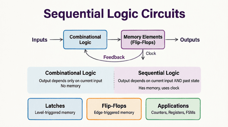
A sequential logic circuit is a digital circuit whose output depends on both the current inputs and the past history of inputs (its current “state”). Unlike combinational circuits, sequential circuits contain memory elements (like flip-flops) and often use a clock signal to synchronize state changes, allowing them to store data and perform time-dependent operations.
Combinational vs. Sequential Logic: The Core Difference
To truly understand sequential logic, one must first clearly distinguish it from combinational logic. The difference lies entirely in the presence or absence of memory and feedback.
Combinational Logic
In a combinational logic circuit, the output at any given instant is determined exclusively by the combination of inputs present at that exact same instant. There is no memory of past inputs.
- Examples: Adders, multiplexers, decoders, and basic logic gates (AND, OR, XOR).
- Behavior: If you change the input, the output changes immediately (subject only to minor propagation delays). If you remove the input, the output disappears.
Sequential Logic
In a sequential logic circuit, the output is determined by the current inputs and the current state of the circuit. The state is a record of past inputs.
- Examples: Flip-flops, counters, shift registers, and microprocessors.
- Behavior: The circuit can remain in a specific state even after the input that caused it has changed. It requires a feedback mechanism to “remember.”
Comparison Table
| Feature | Combinational Logic | Sequential Logic |
|---|---|---|
| Output Dependency | Current inputs only | Current inputs + Past state |
| Memory | No memory elements | Contains memory elements |
| Feedback | No feedback loops | Contains feedback loops |
| Clock Signal | Not required | Usually required (Synchronous) |
| Speed | Generally faster (no clock delay) | Limited by clock frequency |
| Complexity | Simpler to design and analyze | More complex, requires state analysis |
| Examples | Half-adder, Decoder | Counter, Flip-Flop, RAM |
What is the difference between combinational and sequential logic?
Combinational logic outputs depend only on current inputs and have no memory. Sequential logic outputs depend on both current inputs and past states, utilizing memory elements (like flip-flops) and feedback loops to store information over time.
The Concept of Memory and Feedback
How does a circuit actually “remember” something? In digital electronics, memory is achieved through feedback.
Feedback occurs when the output of a logic gate or circuit is routed back to its own input. This creates a loop where the circuit’s future behavior is influenced by its current output.
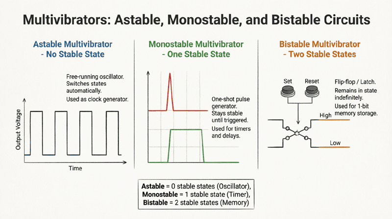
The Bistable Element
The simplest form of memory in digital logic is the bistable multivibrator, commonly known as a latch or flip-flop. A bistable circuit has two stable states: logic ‘0’ (LOW) and logic ‘1’ (HIGH).
Imagine two NOT gates (inverters) connected in a loop: the output of the first feeds the input of the second, and the output of the second feeds the input of the first.
- If the first gate outputs a ‘1’, the second gate outputs a ‘0’, which feeds back to keep the first gate’s output at ‘1’.
- The circuit is “locked” or “latched” in this state. It will remain in this state indefinitely as long as power is applied, effectively storing one bit of data.
By adding control inputs (like Set and Reset) to this basic feedback loop, we can force the circuit to change states, allowing us to write and store data. This basic principle of feedback is the foundation of all digital memory, from a single flip-flop to gigabytes of RAM.
The Role of the Clock Signal
In complex sequential circuits, memory elements must change their state in a coordinated, predictable manner. If every flip-flop in a computer changed state the exact microsecond its input changed, the system would descend into chaos. To prevent this, sequential circuits use a clock signal.
What is a Clock Signal?
A clock signal is a continuous, periodic square wave that oscillates between HIGH (1) and LOW (0). The frequency of this oscillation (measured in Hertz) dictates the speed at which the digital system operates (e.g., a 3.0 GHz processor has a clock that ticks 3 billion times per second).
Synchronous vs. Asynchronous Sequential Circuits
1. Synchronous Sequential Circuits:
In synchronous circuits, the state of the memory elements changes only at specific, discrete times dictated by the clock signal.
- Edge-Triggered: Most modern synchronous circuits are edge-triggered. The state changes only on the rising edge (transition from LOW to HIGH) or the falling edge (transition from HIGH to LOW) of the clock pulse.
- Advantages: Highly predictable, easy to design, prevents race conditions, and allows for complex, high-speed systems.
2. Asynchronous Sequential Circuits:
In asynchronous circuits, there is no global clock signal. Memory elements change state immediately when their inputs change.
- Advantages: Can be faster in specific, simple applications because there is no waiting for a clock tick.
- Disadvantages: Highly prone to “race conditions” and “hazards” (glitches), making them very difficult to design and debug for complex systems. They are rarely used in modern large-scale digital design.
Why do sequential circuits need a clock signal?
A clock signal synchronizes the state changes in a sequential circuit. It ensures that all memory elements (flip-flops) update their stored data at the exact same, predictable moment (usually on the rising or falling edge of the clock), preventing data corruption and race conditions.
Basic Building Blocks: Latches vs. Flip-Flops
The fundamental memory elements in sequential logic are latches and flip-flops. While they both store a single bit of data, they differ in how they respond to control signals.
Latches (Level-Triggered)
A latch is a level-triggered memory device. Its output can change state whenever its enable (or clock) input is at a specific logic level (e.g., HIGH).
- Behavior: As long as the enable pin is HIGH, the output “follows” or “is transparent to” the input. When the enable pin goes LOW, the output is “latched” and holds its last value.
- Drawback: Because they are level-triggered, latches can be susceptible to glitches if the input changes multiple times while the enable pin is HIGH.
Flip-Flops (Edge-Triggered)
A flip-flop is an edge-triggered memory device. It only samples its inputs and updates its output at the exact moment the clock signal transitions (either rising edge or falling edge).
- Behavior: For the vast majority of the clock cycle, the flip-flop ignores changes at its input. It only “looks” at the input for a fraction of a nanosecond during the clock edge.
- Advantage: This edge-triggering makes flip-flops highly reliable and immune to input glitches, which is why they are the standard building block for synchronous sequential circuits.
Common Types:
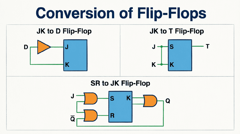
- SR (Set-Reset): The basic memory element.
- D (Data/Delay): Stores the value of the D input on the clock edge.
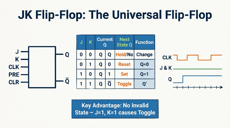
- JK: An enhanced SR flip-flop that toggles its state when both inputs are HIGH.
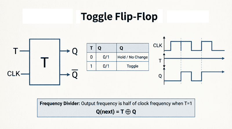
- T (Toggle): Toggles its output state on every clock pulse.
Finite State Machines (FSMs)
When we combine combinational logic (for decision making) with sequential logic (for memory), we create a Finite State Machine (FSM). An FSM is a mathematical model of computation used to design both computer programs and sequential logic circuits.
An FSM consists of:
- A finite number of states.
- A start state.
- Transitions between states based on inputs.
- Outputs based on the current state and/or inputs.
FSMs are visually represented using State Diagrams, where circles represent states and arrows represent transitions.
Moore vs. Mealy Machines
There are two primary types of FSMs, distinguished by how their outputs are generated:
1. Moore Machine:
- The output depends only on the current state.
- Inputs only affect the next state, not the current output.
- Advantage: Outputs are stable and only change on clock edges, making them less prone to glitches.
- Disadvantage: May require more states than a Mealy machine to perform the same task.
2. Mealy Machine:
- The output depends on both the current state and the current inputs.
- Advantage: Often requires fewer states and can react to inputs faster (without waiting for the next clock edge).
- Disadvantage: Outputs can change asynchronously with inputs, potentially causing transient glitches.
What is the difference between Moore and Mealy machines?
In a Moore machine, the output depends strictly on the current state. In a Mealy machine, the output depends on both the current state and the current input. Moore machines are generally safer from glitches, while Mealy machines often require fewer states.
Practical Applications of Sequential Logic
Sequential logic circuits are the engines that drive modern technology. Their ability to store and process data over time makes them indispensable.
1. Data Storage (Memory)
The most direct application of sequential logic is memory. A single flip-flop stores one bit. By combining millions or billions of flip-flops (or capacitor-based DRAM cells controlled by sequential logic), we create the RAM and cache memory in computers and smartphones.
2. Counters and Timers
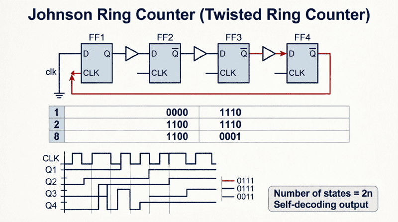
Counters are sequential circuits that cycle through a specific sequence of states. They are used in digital clocks, frequency dividers, and event counting. A timer is essentially a counter driven by a precise clock signal.
3. Shift Registers
Shift registers are chains of flip-flops used to store and move data. They are crucial for serial-to-parallel and parallel-to-serial data conversion, widely used in communication protocols like UART, SPI, and USB.
4. Microprocessors and CPUs
The Control Unit of a CPU is essentially a massive, complex Finite State Machine. It uses sequential logic to fetch instructions from memory, decode them, and execute them in the correct sequence, step by step.
5. Sequence Detectors
Sequential circuits are used in security systems and communication receivers to detect specific patterns or “passwords” in a serial stream of data, ignoring all other random inputs.
Sequential logic circuits represent the leap from simple, reactive digital systems to complex, intelligent computing machines. By introducing the concepts of memory, feedback, and time (via the clock signal), sequential logic allows circuits to store data, remember past events, and execute complex, multi-step algorithms.
Key takeaways from this guide include:
- Core Definition: Sequential logic outputs depend on both current inputs and past states (memory).
- Memory Mechanism: Memory is achieved through feedback loops, primarily using bistable elements like latches and flip-flops.
- Synchronization: The clock signal is vital in synchronous circuits to coordinate state changes and prevent data corruption.
- Latches vs. Flip-Flops: Latches are level-triggered (transparent), while flip-flops are edge-triggered (reliable), making flip-flops the standard for modern design.
- Finite State Machines: FSMs (Moore and Mealy models) combine combinational and sequential logic to create complex, state-dependent behaviors.
Understanding sequential logic is the gateway to mastering digital system design. Whether you are programming an FPGA, designing a microcontroller, or simply trying to understand how a computer remembers your files, the principles of sequential logic are the fundamental rules governing the digital world.