Johnson Ring Counter
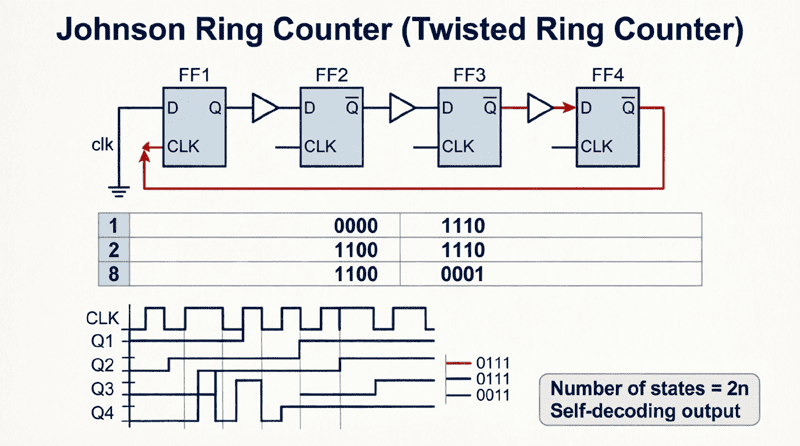
Johnson Ring Counter: Complete Guide to Twisted Ring Counter Operation
Introduction to Johnson Ring Counters
The Johnson ring counter, also known as a twisted ring counter or switch-tail ring counter, is a specialized type of shift register-based counter that offers unique advantages over standard binary counters and ring counters. By feeding the inverted output of the last flip flop back to the input of the first flip flop, the Johnson counter creates a distinctive counting sequence that makes it ideal for timing applications, sequence generation, and decoded outputs.
Unlike a standard ring counter that circulates a single ‘1’ bit through the flip flops, the Johnson counter generates a sequence where bits gradually fill with ‘1’s and then gradually clear back to ‘0’s. This creates a “walking” pattern that provides several benefits:
- Self-decoding outputs: Each state can be decoded with simple 2-input gates
- Glitch-free operation: Only one bit changes at a time
- Efficient use of flip flops: An N-bit Johnson counter has 2N states
- Simple implementation: Requires minimal external logic
Johnson counters are widely used in digital systems for applications such as timing signal generation, stepper motor control, sequence controllers, and frequency division. They are particularly valuable when you need a specific number of timing phases or when glitch-free decoded outputs are critical.
This comprehensive guide will explore the architecture, operation, truth tables, decoding logic, and practical applications of Johnson ring counters, complete with visual diagrams and real-world examples.
What is a Johnson Ring Counter?
A Johnson ring counter (or twisted ring counter) is a shift register-based counter where the inverted output of the last flip flop is fed back to the input of the first flip flop. An N-bit Johnson counter cycles through 2N unique states, creating a “walking” pattern of 1s and 0s. It provides glitch-free, self-decoding outputs ideal for timing and sequence generation applications.
Architecture and Circuit Configuration
The Johnson ring counter is built from a cascade of D flip flops (or JK flip flops configured as D flip flops) connected in a specific feedback configuration.
The “Twisted” Feedback
The defining characteristic of a Johnson counter is its feedback connection:
- The Q output of the last flip flop is inverted (using a NOT gate or using the Q’ output)
- This inverted signal is fed back to the D input of the first flip flop
- All flip flops share a common clock signal
This “twist” in the feedback loop is what distinguishes the Johnson counter from a standard ring counter (where the non-inverted output is fed back).
Basic 4-Bit Johnson Counter
A 4-bit Johnson counter consists of:
- 4 D flip flops (FF0, FF1, FF2, FF3)
- Connections: Q0→D1, Q1→D2, Q2→D3, Q3’→D0
- Common clock signal to all flip flops
- Optional asynchronous reset/clear to initialize the counter
The circuit is remarkably simple, requiring no external logic gates for the basic counting operation (except for the inversion, which is typically available as the Q’ output of the flip flop).
How is a Johnson counter different from a standard ring counter?
In a standard ring counter, the non-inverted output (Q) of the last flip flop feeds back to the first flip flop’s input, circulating a single ‘1’. In a Johnson counter, the inverted output (Q’) feeds back, creating a “twisted” loop that generates a sequence of 2N states where bits gradually fill with 1s and then clear back to 0s.
Operation and Counting Sequence
Understanding how a Johnson counter operates is best done by tracing through its counting sequence. Let’s examine a 4-bit Johnson counter starting from the reset state (all 0s).
Step-by-Step Operation
Initial State (Reset): Q0=0, Q1=0, Q2=0, Q3=0
- Q3′ = 1 (inverted)
- D0 = Q3′ = 1
Clock Pulse 1:
- FF0 captures D0=1 → Q0=1
- FF1 captures Q0=0 → Q1=0
- FF2 captures Q1=0 → Q2=0
- FF3 captures Q2=0 → Q3=0
- State: 1000
Clock Pulse 2:
- Q3′ = 1
- D0 = 1
- FF0 captures 1 → Q0=1
- FF1 captures Q0=1 → Q1=1
- FF2 captures Q1=0 → Q2=0
- FF3 captures Q2=0 → Q3=0
- State: 1100
Clock Pulse 3:
- Q3′ = 1
- D0 = 1
- FF0 captures 1 → Q0=1
- FF1 captures Q0=1 → Q1=1
- FF2 captures Q1=1 → Q2=1
- FF3 captures Q2=0 → Q3=0
- State: 1110
Clock Pulse 4:
- Q3′ = 1
- D0 = 1
- FF0 captures 1 → Q0=1
- FF1 captures Q0=1 → Q1=1
- FF2 captures Q1=1 → Q2=1
- FF3 captures Q2=1 → Q3=1
- State: 1111
Clock Pulse 5:
- Q3′ = 0 (now inverted!)
- D0 = 0
- FF0 captures 0 → Q0=0
- FF1 captures Q0=1 → Q1=1
- FF2 captures Q1=1 → Q2=1
- FF3 captures Q2=1 → Q3=1
- State: 0111
Clock Pulse 6:
- Q3′ = 0
- D0 = 0
- FF0 captures 0 → Q0=0
- FF1 captures Q0=0 → Q1=0
- FF2 captures Q1=1 → Q2=1
- FF3 captures Q2=1 → Q3=1
- State: 0011
Clock Pulse 7:
- Q3′ = 0
- D0 = 0
- FF0 captures 0 → Q0=0
- FF1 captures Q0=0 → Q1=0
- FF2 captures Q1=0 → Q2=0
- FF3 captures Q2=1 → Q3=1
- State: 0001
Clock Pulse 8:
- Q3′ = 0
- D0 = 0
- FF0 captures 0 → Q0=0
- FF1 captures Q0=0 → Q1=0
- FF2 captures Q1=0 → Q2=0
- FF3 captures Q2=0 → Q3=0
- State: 0000 (Back to initial state!)
The Complete Sequence
The 4-bit Johnson counter cycles through these 8 states:
- 0000
- 1000
- 1100
- 1110
- 1111
- 0111
- 0011
- 0001
- 0000 (repeat)
Notice the pattern:
- The ‘1’s “walk” from left to right, filling the register
- Once full (1111), the ‘0’s “walk” from left to right, clearing the register
- This creates a smooth, glitch-free transition between states
How many states does an N-bit Johnson counter have?
An N-bit Johnson counter has 2N unique states. For example, a 4-bit Johnson counter has 8 states, a 5-bit counter has 10 states, and so on. This is twice as many states as a standard ring counter (which has N states) but half as many as a binary counter (which has 2^N states).
Truth Table and State Diagram
Truth Table for 4-Bit Johnson Counter
| Clock Pulse | Q0 | Q1 | Q2 | Q3 | Decimal |
|---|---|---|---|---|---|
| 0 (Reset) | 0 | 0 | 0 | 0 | 0 |
| 1 | 1 | 0 | 0 | 0 | 1 |
| 2 | 1 | 1 | 0 | 0 | 2 |
| 3 | 1 | 1 | 1 | 0 | 3 |
| 4 | 1 | 1 | 1 | 1 | 4 |
| 5 | 0 | 1 | 1 | 1 | 5 |
| 6 | 0 | 0 | 1 | 1 | 6 |
| 7 | 0 | 0 | 0 | 1 | 7 |
| 8 | 0 | 0 | 0 | 0 | 0 (repeat) |
State Diagram
The state diagram of a Johnson counter is a simple loop connecting all 2N states in sequence. Each transition occurs on a clock edge, and the counter automatically cycles through all states before returning to the start.
Key Characteristics
1. Self-Correcting (with proper initialization):
If the counter is properly reset to 0000, it will cycle through all valid states. However, if it enters an invalid state (due to noise or power-up conditions), it may not self-correct without additional logic.
2. Glitch-Free Transitions:
Only one flip flop changes state on each clock pulse, making Johnson counters ideal for applications requiring glitch-free decoded outputs.
3. Decoded Outputs:
Each of the 2N states can be decoded using simple 2-input AND gates, as we’ll explore in the next section.
Decoding Logic and Output Generation
One of the major advantages of Johnson counters is their self-decoding nature. Unlike binary counters that require complex decoding logic (multiple-input gates), each state of a Johnson counter can be decoded using simple 2-input AND gates.
Decoding Principle
In a Johnson counter, each state has a unique pattern where:
- Two adjacent flip flops have a unique combination that doesn’t repeat in any other state
- This combination can be detected with a simple 2-input AND gate
Decoding a 4-Bit Johnson Counter
For a 4-bit Johnson counter with 8 states, we need 8 decoding gates:
| State | Q0 | Q1 | Q2 | Q3 | Decoding Logic |
|---|---|---|---|---|---|
| 0 | 0 | 0 | 0 | 0 | Q0′ · Q3′ |
| 1 | 1 | 0 | 0 | 0 | Q0 · Q1′ |
| 2 | 1 | 1 | 0 | 0 | Q1 · Q2′ |
| 3 | 1 | 1 | 1 | 0 | Q2 · Q3′ |
| 4 | 1 | 1 | 1 | 1 | Q0 · Q3 |
| 5 | 0 | 1 | 1 | 1 | Q0′ · Q1 |
| 6 | 0 | 0 | 1 | 1 | Q1′ · Q2 |
| 7 | 0 | 0 | 0 | 1 | Q2′ · Q3 |
Example: To decode State 3 (1110):
- Use a 2-input AND gate
- Connect Q2 (which is 1) and Q3′ (which is 1 when Q3=0)
- Output is HIGH only when the counter is in State 3
This simplicity makes Johnson counters extremely attractive for applications requiring decoded timing signals, such as stepper motor control or sequential process control.
Decoded Output Waveforms
When you decode all states of a Johnson counter, you get a set of non-overlapping pulses, each one clock cycle wide, that cycle through in sequence. This is perfect for:
- Generating timing signals for sequential operations
- Controlling multiphase systems
- Creating ring oscillator-like behavior with precise timing
Why are Johnson counters easy to decode?
Johnson counters are self-decoding because each state has a unique combination of two adjacent flip flops that can be detected with a simple 2-input AND gate. This is much simpler than binary counters, which require complex multi-input decoding logic.
Johnson Counter vs. Ring Counter vs. Binary Counter
Understanding when to use a Johnson counter requires comparing it to other counter types.
Comparison Table
| Feature | Johnson Counter | Ring Counter | Binary Counter |
|---|---|---|---|
| Number of States | 2N | N | 2^N |
| Flip Flops Required | N | N | log₂(N) |
| Decoding Complexity | Simple (2-input gates) | Simple (1-input) | Complex (multi-input) |
| Glitch-Free | Yes | Yes | No (multiple bits change) |
| State Utilization | Moderate | Poor | Excellent |
| Power Consumption | Moderate | High (many 1s) | Low |
| Applications | Timing, sequence gen. | Simple sequencing | General counting |
When to Use Each Type
Use a Johnson Counter when:
- You need decoded outputs with simple logic
- Glitch-free operation is critical
- You need more states than a ring counter but simpler decoding than a binary counter
- You’re generating timing sequences or controlling multiphase systems
Use a Ring Counter when:
- You need the simplest possible implementation
- You only need N states
- Power consumption is not a concern
- You’re doing simple circular sequencing
Use a Binary Counter when:
- You need to count to large numbers efficiently
- You need maximum state utilization
- You have complex decoding requirements anyway
- You’re implementing arithmetic operations
Practical Applications
Johnson counters find applications in a wide variety of digital systems:
1. Stepper Motor Control
Stepper motors require a specific sequence of coil activations to rotate. A Johnson counter naturally generates this sequence:
- Each decoded output controls one motor coil
- The “walking” pattern of 1s matches the motor’s stepping sequence
- Glitch-free operation prevents motor jitter
Example: A 4-phase stepper motor can be controlled with a 4-bit Johnson counter, providing 8 distinct steps per cycle.
2. Timing Signal Generation
In digital systems that require multiple non-overlapping timing phases:
- Each decoded output provides one timing phase
- The phases are naturally sequential and non-overlapping
- Perfect for controlling sequential processes, multiplexers, or state machines
3. Frequency Division
A Johnson counter divides the input clock frequency by 2N:
- A 4-bit Johnson counter divides by 8
- A 5-bit Johnson counter divides by 10
- The output has a 50% duty cycle (for even-numbered stages)
This makes Johnson counters useful as frequency dividers in communication systems and clock generation circuits.
4. Sequence Controllers
In industrial automation and process control:
- Each state represents one step in a process
- Decoded outputs activate specific actuators or valves
- The counter advances through the sequence automatically
5. Digital-to-Analog Conversion (DAC)
Johnson counters can be used in simple DAC circuits:
- The “walking” pattern of 1s creates a staircase waveform
- When passed through a low-pass filter, this creates a smooth analog ramp
- Useful in function generators and waveform synthesis
6. LED Chasers and Display Effects
The visual pattern of a Johnson counter is perfect for LED effects:
- LEDs light up sequentially, then turn off sequentially
- Creates a “fill and drain” visual effect
- Popular in decorative lighting and status indicators
Popular Johnson Counter ICs
While Johnson counters can be built from discrete flip flops, several integrated circuits implement this functionality:
74HC4017 (Decade Counter with Decoded Outputs)
The 74HC4017 is one of the most popular Johnson counter ICs:
- 5-bit Johnson counter (10 states)
- 10 decoded outputs (Q0-Q9)
- Carry-out output for cascading
- Reset and Clock Enable inputs
- Applications: LED chasers, sequence generators, frequency dividers
This IC is essentially a 5-bit Johnson counter with all the decoding logic built-in, making it incredibly easy to use.
74HC4022 (Octal Counter with Decoded Outputs)
Similar to the 74HC4017 but with 8 outputs:
- 4-bit Johnson counter (8 states)
- 8 decoded outputs (Q0-Q7)
- Similar pinout and functionality to the 4017
CD4017 (CMOS Decade Counter)
The classic CMOS version of the 4017:
- Same functionality as 74HC4017
- Wider voltage range (3V-15V)
- Lower speed than HC series
- Still widely available and popular
Design Considerations and Best Practices
Initialization and Reset
Johnson counters must be properly initialized to enter the correct counting sequence. If the counter powers up in an invalid state (e.g., 1010), it may cycle through invalid states indefinitely.
Solutions:
- Power-on Reset Circuit: Use an RC circuit or dedicated reset IC to assert the reset pin when power is applied
- Self-Correcting Logic: Add additional logic to detect invalid states and force the counter back to a valid state
- Synchronous Reset: Use a synchronous reset input to initialize the counter on the first clock edge
Clock Frequency
Johnson counters, like all sequential circuits, have a maximum clock frequency determined by:
- Flip flop propagation delay
- Setup and hold times
- Decoding logic delay (if used)
Ensure your clock frequency is well within the specifications of your flip flops or IC.
Cascading Counters
To create longer sequences, you can cascade Johnson counters:
- Connect the carry-out or last decoded output of the first counter to the clock input of the second counter
- This creates a longer total sequence (e.g., two 4017s create a 20-state sequence)
The Johnson ring counter is an elegant and practical solution for a wide range of digital design challenges. By simply “twisting” the feedback of a shift register, it creates a versatile counter that balances simplicity, decoded outputs, and state count.
Key takeaways from this guide include:
- Architecture: A Johnson counter feeds the inverted output of the last flip flop back to the first flip flop’s input, creating a “twisted” loop.
- Counting Sequence: An N-bit Johnson counter cycles through 2N unique states, with 1s “walking” through the register and then clearing back to 0s.
- Self-Decoding: Each state can be decoded with a simple 2-input AND gate, making Johnson counters much easier to decode than binary counters.
- Glitch-Free Operation: Only one flip flop changes per clock cycle, ensuring clean, glitch-free decoded outputs.
- Applications: Stepper motor control, timing signal generation, frequency division, sequence controllers, and LED effects.
- Popular ICs: The 74HC4017 (decade counter) and 74HC4022 (octal counter) are industry-standard Johnson counter ICs with built-in decoding.
Whether you’re building a simple LED chaser or a complex industrial controller, the Johnson ring counter provides an efficient, reliable, and easy-to-implement solution for sequential logic design.