Electromagnetic Induction
Electromagnetic Induction: Complete Guide to Faraday’s and Lenz’s Laws
Introduction to Electromagnetic Induction
If electromagnetism taught us that electric currents create magnetic fields, electromagnetic induction reveals the beautiful symmetry of nature: changing magnetic fields create electric currents. This fundamental principle, discovered independently by Michael Faraday in England and Joseph Henry in the United States in 1831, is the foundation of virtually all electrical power generation and distribution.
Every time you flip a light switch, charge your phone, or start your car, you’re benefiting from electromagnetic induction. Power plants use it to generate electricity, transformers use it to change voltage levels, and wireless chargers use it to transfer energy without physical connections.
Electromagnetic induction is governed by two fundamental laws: Faraday’s Law of Induction, which quantifies the induced voltage, and Lenz’s Law, which determines the direction of the induced current. Together, these laws explain how generators convert mechanical energy into electrical energy, how transformers transfer power between circuits, and how induction motors create torque without electrical connections to the rotor.
This comprehensive guide will explore the principles, mathematics, and applications of electromagnetic induction, providing you with a complete understanding of this cornerstone of electrical engineering.
What is Electromagnetic Induction?
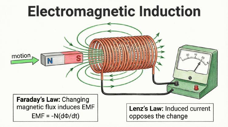
Electromagnetic induction is the process by which a changing magnetic field induces an electromotive force (EMF) or voltage in a conductor. Discovered by Michael Faraday in 1831, it is governed by Faraday’s Law (induced EMF is proportional to the rate of change of magnetic flux) and Lenz’s Law (the induced current opposes the change that created it).
Faraday’s Law of Electromagnetic Induction
The Discovery
In 1831, Michael Faraday conducted a series of groundbreaking experiments. He wrapped two coils of wire around opposite sides of an iron ring. When he connected a battery to one coil (the primary), he observed a brief deflection in a galvanometer connected to the other coil (the secondary).
Crucially, the deflection occurred only when the current was changing—when the battery was connected or disconnected. A steady current in the primary produced no effect in the secondary. Faraday realized that it was the changing magnetic field, not the magnetic field itself, that induced the voltage.
Faraday’s Law Statement
Faraday’s Law of Electromagnetic Induction states:
“The induced electromotive force (EMF) in any closed circuit is equal to the negative of the time rate of change of the magnetic flux through the circuit.”
Mathematical Formulation
For a single loop of wire:
$\mathcal{E} = -\frac{d\Phi_B}{dt}$
Where:
- $\mathcal{E}$ = Induced electromotive force (EMF) in Volts (V)
- $\Phi_B$ = Magnetic flux in Webers (Wb)
- $t$ = Time in seconds (s)
- $d\Phi_B/dt$ = Rate of change of magnetic flux
For a coil with N turns:
$\mathcal{E} = -N \frac{d\Phi_B}{dt}$
The negative sign represents Lenz’s Law (discussed below), indicating that the induced EMF opposes the change in flux.
Ways to Change Magnetic Flux
Since $\Phi_B = B \cdot A \cdot \cos(\theta)$, there are three ways to induce an EMF:
- Change the Magnetic Field Strength (B): Vary the strength of the external magnetic field (e.g., using an electromagnet with varying current).
- Change the Area (A): Change the area of the loop exposed to the magnetic field (e.g., expanding or contracting a loop, or moving a conductor through a field).
- Change the Orientation (θ): Rotate the loop relative to the magnetic field (this is how generators work).
What does Faraday’s Law state?
Faraday’s Law states that the induced EMF in a circuit is proportional to the rate of change of magnetic flux through the circuit: $\mathcal{E} = -N(d\Phi/dt)$. A changing magnetic field—whether by varying field strength, loop area, or orientation—induces a voltage.
Lenz’s Law: The Direction of Induced Current
The Principle of Opposition
While Faraday’s Law tells us the magnitude of the induced EMF, Lenz’s Law (formulated by Heinrich Lenz in 1834) tells us the direction:
“The direction of the induced current is such that it opposes the change in magnetic flux that produced it.”
This is a consequence of the conservation of energy. If the induced current reinforced the change instead of opposing it, we would get a perpetual motion machine—the induced current would create a stronger field, which would induce more current, and so on, creating energy from nothing. Nature doesn’t allow this.
Applying Lenz’s Law
To determine the direction of induced current:
- Identify the change: Is the magnetic flux increasing or decreasing?
- Determine the opposition: The induced current will create a magnetic field that opposes this change.
- If flux is increasing, the induced field points opposite to the external field.
- If flux is decreasing, the induced field points in the same direction as the external field (trying to maintain it).
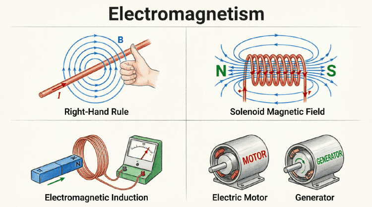
- Use the Right-Hand Rule: Curl your right-hand fingers in the direction of the induced current; your thumb points in the direction of the induced magnetic field.
Example: Magnet Moving Toward a Coil
Imagine pushing the North pole of a bar magnet toward a coil of wire:
- Change: Magnetic flux through the coil is increasing (more field lines entering).
- Opposition: The coil must create a magnetic field that repels the approaching North pole.
- Induced Pole: To repel a North pole, the face of the coil must become a North pole.
- Current Direction: Using the Right-Hand Rule for coils, if the face is North, the current must flow counter-clockwise (as viewed from the magnet side).
If you pull the magnet away, the flux decreases. The coil now tries to attract the retreating North pole by becoming a South pole, reversing the current direction to clockwise.
What is Lenz’s Law?
Lenz’s Law states that the direction of induced current always opposes the change in magnetic flux that created it. This ensures conservation of energy—the induced current creates a magnetic field that resists the motion or change causing the induction.
Motional EMF: Conductors Moving in Magnetic Fields
When a conductor moves through a magnetic field, the free electrons inside experience a magnetic force (Lorentz force), causing them to accumulate at one end of the conductor. This separation of charge creates a potential difference called motional EMF.
Formula for Motional EMF
For a straight conductor of length L moving with velocity v perpendicular to a uniform magnetic field B:
$\mathcal{E} = B \cdot L \cdot v$
Where:
- $\mathcal{E}$ = Induced EMF in Volts (V)
- $B$ = Magnetic flux density in Tesla (T)
- $L$ = Length of conductor in meters (m)
- $v$ = Velocity of conductor in m/s
If the motion is at an angle θ to the field:
$\mathcal{E} = B \cdot L \cdot v \cdot \sin(\theta)$
Physical Mechanism
As the conductor moves through the field, free electrons experience the Lorentz force:
$F = q(v \times B)$
This force pushes electrons to one end of the conductor, creating a negative charge accumulation at one end and a positive charge at the other. This charge separation creates an electric field that opposes further electron movement, establishing an equilibrium voltage—the motional EMF.
Applications
- Electric generators: Rotating coils cut magnetic field lines, inducing EMF
- Flow meters: Conductive fluids moving through magnetic fields induce voltage proportional to flow rate
- Rail guns: Motional EMF and Lorentz force accelerate projectiles
Self-Inductance and Mutual Inductance
Self-Inductance (L)
When the current in a coil changes, the changing magnetic field induces an EMF in the same coil. This phenomenon is called self-induction, and the property is called self-inductance.
Definition: Self-inductance L is the ratio of the induced EMF to the rate of change of current:
$\mathcal{E} = -L \frac{dI}{dt}$
Where:
- $L$ = Self-inductance in Henrys (H)
- $dI/dt$ = Rate of change of current in A/s
For a solenoid:
$L = \frac{\mu N^2 A}{l}$
Where:
- $N$ = Number of turns
- $A$ = Cross-sectional area
- $l$ = Length of solenoid
- $\mu$ = Permeability of core material
Physical Meaning: An inductance of 1 Henry means that a current change of 1 A/s induces an EMF of 1 Volt.
Mutual Inductance (M)
When two coils are placed near each other, a changing current in the primary coil induces an EMF in the secondary coil. This is mutual induction, quantified by mutual inductance M.
$\mathcal{E}_2 = -M \frac{dI_1}{dt}$
Where:
- $M$ = Mutual inductance in Henrys (H)
- $dI_1/dt$ = Rate of change of current in primary coil
Transformer Action: This is the fundamental principle of transformers, where energy is transferred from primary to secondary via mutual inductance.
Coupling Coefficient (k):
The efficiency of coupling between two coils is described by:
$k = \frac{M}{\sqrt{L_1 L_2}}$
Where k ranges from 0 (no coupling) to 1 (perfect coupling).
What is the difference between self-inductance and mutual inductance?
Self-inductance (L) is the induction of EMF in a coil due to its own changing current. Mutual inductance (M) is the induction of EMF in one coil due to the changing current in a nearby coil. Self-inductance is the basis for inductors; mutual inductance is the basis for transformers.
Practical Applications of Electromagnetic Induction
1. Electric Generators
Generators convert mechanical energy into electrical energy using electromagnetic induction. A coil (armature) rotates in a magnetic field, continuously changing the magnetic flux through the coil, which induces an alternating EMF.
AC Generator (Alternator): Produces sinusoidal AC voltage. The frequency depends on rotation speed: $f = (N \times P) / 120$, where N is RPM and P is number of poles.
DC Generator: Uses a commutator to convert the induced AC into DC output.
2. Transformers
Transformers use mutual inductance to transfer electrical energy between circuits at different voltage levels. An AC current in the primary coil creates a changing magnetic field, which induces voltage in the secondary coil.
Voltage Ratio: $\frac{V_s}{V_p} = \frac{N_s}{N_p}$
Where $N_s$ and $N_p$ are the number of turns in secondary and primary coils.
3. Induction Motors
Induction motors use electromagnetic induction to create torque without electrical connections to the rotor. A rotating magnetic field in the stator induces currents in the rotor conductors, which create their own magnetic field that interacts with the stator field to produce rotation.
4. Induction Heating
High-frequency AC in a coil creates a rapidly changing magnetic field. When a conductive material is placed in this field, eddy currents are induced, heating the material through resistive (I²R) losses. Used in metal hardening, melting, and cooking (induction stovetops).
5. Wireless Charging
Inductive charging pads use mutual inductance to transfer energy wirelessly. An AC current in the transmitter coil creates a magnetic field that induces voltage in the receiver coil in your device.
6. Magnetic Flow Meters
Conductive fluids flowing through a pipe with an applied magnetic field induce a voltage proportional to flow velocity, allowing non-invasive flow measurement.
Eddy Currents
When a conductor is exposed to a changing magnetic field (or moves through a magnetic field), circulating currents called eddy currents are induced within the bulk of the conductor.
Effects of Eddy Currents
Negative Effects:
- Energy Loss: Eddy currents dissipate energy as heat (I²R losses)
- Reduced Efficiency: In transformers and motors, eddy currents reduce efficiency
- Heating: Can cause unwanted heating in magnetic cores
Mitigation:
- Laminated Cores: Transformer and motor cores are made of thin, insulated steel laminations perpendicular to the expected eddy current path, increasing resistance and reducing current magnitude.
Positive Applications:
- Eddy Current Brakes: Used in trains and roller coasters; eddy currents create opposing magnetic fields that slow motion without physical contact
- Metal Detectors: Eddy currents induced in metal objects create detectable secondary fields
- Non-Destructive Testing: Eddy current testing detects cracks and defects in conductive materials
Practical Examples and Calculations
Example 1: Calculating Induced EMF (Faraday’s Law)
Problem: A coil of 200 turns experiences a change in magnetic flux from 0.05 Wb to 0.15 Wb in 0.1 seconds. Calculate the induced EMF.
Solution:
Given:
- $N = 200$ turns
- $\Phi_1 = 0.05 \text{ Wb}$
- $\Phi_2 = 0.15 \text{ Wb}$
- $\Delta t = 0.1 \text{ s}$
Step 1: Calculate change in flux
$\Delta \Phi = \Phi_2 – \Phi_1 = 0.15 – 0.05 = 0.10 \text{ Wb}$
Step 2: Calculate rate of change
$\frac{\Delta \Phi}{\Delta t} = \frac{0.10}{0.1} = 1.0 \text{ Wb/s}$
Step 3: Apply Faraday’s Law
$\mathcal{E} = -N \frac{\Delta \Phi}{\Delta t}$
$\mathcal{E} = -200 \times 1.0$
$\mathcal{E} = -200 \text{ V}$
Result: The magnitude of induced EMF is 200 Volts. The negative sign indicates the direction opposes the change (Lenz’s Law).
Example 2: Motional EMF
Problem: A 0.5 m long conductor moves at 10 m/s perpendicular to a uniform magnetic field of 0.8 T. Calculate the induced EMF.
Solution:
Given:
- $L = 0.5 \text{ m}$
- $v = 10 \text{ m/s}$
- $B = 0.8 \text{ T}$
- $\theta = 90^\circ$ (perpendicular)
Formula:
$\mathcal{E} = B \cdot L \cdot v \cdot \sin(\theta)$
Calculation:
$\mathcal{E} = 0.8 \times 0.5 \times 10 \times \sin(90^\circ)$
$\mathcal{E} = 0.8 \times 0.5 \times 10 \times 1$
$\mathcal{E} = 4.0 \text{ V}$
Example 3: Self-Inductance and Induced EMF
Problem: A solenoid has 500 turns, a length of 0.2 m, and a cross-sectional area of 0.001 m². The core is air ($\mu_0 = 4\pi \times 10^{-7} \text{ H/m}$). Calculate:
(a) The self-inductance
(b) The induced EMF if the current changes from 0 to 3 A in 0.05 seconds
Solution:
Part (a): Calculate Inductance
Given:
- $N = 500$ turns
- $l = 0.2 \text{ m}$
- $A = 0.001 \text{ m}^2$
- $\mu = \mu_0 = 4\pi \times 10^{-7} \text{ H/m}$
Formula:
$L = \frac{\mu N^2 A}{l}$
Calculation:
$L = \frac{(4\pi \times 10^{-7}) \times 500^2 \times 0.001}{0.2}$
$L = \frac{(1.257 \times 10^{-6}) \times 250000 \times 0.001}{0.2}$
$L = \frac{0.000314}{0.2}$
$L = 0.00157 \text{ H} = 1.57 \text{ mH}$
Part (b): Calculate Induced EMF
Given:
- $\Delta I = 3 – 0 = 3 \text{ A}$
- $\Delta t = 0.05 \text{ s}$
Formula:
$\mathcal{E} = -L \frac{\Delta I}{\Delta t}$
Calculation:
$\mathcal{E} = -0.00157 \times \frac{3}{0.05}$
$\mathcal{E} = -0.00157 \times 60$
$\mathcal{E} = -0.0942 \text{ V} = -94.2 \text{ mV}$
Electromagnetic induction is one of the most profound and practical discoveries in physics. Faraday’s insight that changing magnetic fields create electric currents unlocked the ability to generate electricity on a massive scale, forming the foundation of our modern electrical civilization.
Key takeaways from this guide:
- Faraday’s Law: The induced EMF is proportional to the rate of change of magnetic flux: $\mathcal{E} = -N(d\Phi/dt)$
- Lenz’s Law: The induced current always opposes the change that created it, ensuring conservation of energy.
- Motional EMF: Conductors moving through magnetic fields experience induced voltage: $\mathcal{E} = BLv$
- Self-Inductance: A coil’s own changing current induces EMF in itself, quantified by inductance L (Henrys).
- Mutual Inductance: Changing current in one coil induces EMF in a nearby coil, the principle behind transformers.
- Applications: Generators, transformers, induction motors, wireless charging, and induction heating all rely on electromagnetic induction.
- Eddy Currents: Circulating currents induced in bulk conductors can cause losses (requiring laminated cores) or be exploited for braking and sensing.
Understanding electromagnetic induction is essential for anyone working with electrical power systems, motors, generators, or transformers. It explains how mechanical energy becomes electrical energy, how voltage levels are transformed for efficient transmission, and how wireless energy transfer is possible. As we continue to develop new technologies like wireless power transfer and advanced electric vehicles, the principles discovered by Faraday nearly 200 years ago remain as relevant as ever.