Hall Effect Sensor
Hall Effect Sensor: The Complete Guide to Magnetic Sensing Technology
Introduction to the Hall Effect Sensor
In 1879, a 24-year-old graduate student named Edwin Hall made a discovery that would eventually revolutionize modern electronics. While studying the behavior of conductors in magnetic fields, he noticed that a magnetic field applied perpendicular to a current-carrying conductor creates a measurable voltage difference across the conductor, perpendicular to both the current and the magnetic field. This phenomenon is known as the Hall Effect.
Today, the Hall Effect sensor is a ubiquitous solid-state device that converts magnetic field information into an electrical signal. Unlike mechanical switches or optical sensors, Hall Effect sensors are contactless, immune to dust, dirt, and moisture, and can operate reliably for billions of cycles.
From the anti-lock braking systems (ABS) in your car and the brushless motors in your drone, to the current monitoring in electric vehicle battery packs and the lid-closure detection in your laptop, Hall Effect sensors are silently working everywhere.
This comprehensive guide will explore the underlying physics of the Hall Effect, the mathematical derivation of Hall voltage, the different types of Hall sensors, their key characteristics, and their vast array of practical applications in modern engineering.
What is a Hall Effect Sensor?
A Hall Effect sensor is a solid-state device that detects the presence, strength, and polarity of a magnetic field and converts it into an electrical voltage or digital signal. It operates based on the Hall Effect, where a magnetic field applied perpendicular to a current-carrying semiconductor causes charge carriers to deflect, creating a measurable transverse voltage (Hall voltage).
The Physics of the Hall Effect
To understand how a Hall Effect sensor works, we must look at the behavior of charge carriers (electrons or holes) inside a conductor or semiconductor when subjected to a magnetic field.
The Lorentz Force in Action
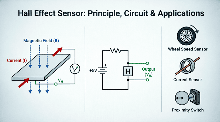
Imagine a flat, rectangular piece of semiconductor material (like silicon or gallium arsenide). We pass a steady direct current ($I$) through it from left to right. The charge carriers (let’s assume electrons for an N-type semiconductor) drift from right to left.
Now, we apply a uniform magnetic field ($B$) perpendicular to the flat surface of the material (e.g., pointing downward into the material).
According to the Lorentz Force Law, a moving charge in a magnetic field experiences a force perpendicular to both its velocity and the magnetic field:
$F = q(v \times B)$
Where:
- $F$ = Magnetic force on the charge
- $q$ = Charge of the carrier (e.g., $-1.6 \times 10^{-19}$ C for an electron)
- $v$ = Drift velocity of the charge carrier
- $B$ = Magnetic flux density
Charge Accumulation and Hall Voltage
As the electrons drift through the material, the downward magnetic field pushes them toward one edge of the semiconductor (the Lorentz force deflects them sideways).
This deflection causes a buildup of negative charge on one edge and a corresponding deficit of electrons (positive charge) on the opposite edge. This charge separation creates an internal electric field ($E_H$) across the width of the material.
This electric field exerts an opposing electric force ($F_E = qE_H$) on the charge carriers. Equilibrium is quickly reached when the magnetic deflection force is exactly balanced by the electric repulsion force:
$qE_H = qvB$ $\rightarrow$ $E_H = vB$
This transverse electric field manifests as a measurable potential difference across the width of the material, known as the Hall Voltage ($V_H$).
What causes the Hall Voltage?
The Hall voltage is caused by the Lorentz force deflecting moving charge carriers to one side of a conductor or semiconductor when a magnetic field is applied perpendicularly. This creates a charge imbalance, generating a transverse electric field and a measurable voltage difference across the material.
The Hall Voltage Formula
The magnitude of the Hall voltage can be derived from the equilibrium condition and the definition of current. The standard formula for Hall voltage is:
$V_H = \frac{I \cdot B}{n \cdot t \cdot e}$
Alternatively, it is often expressed using the Hall Coefficient ($R_H$):
$V_H = R_H \frac{I \cdot B}{t}$
Where:
- $V_H$ = Hall voltage in Volts (V)
- $I$ = Control current through the sensor in Amperes (A)
- $B$ = Magnetic flux density perpendicular to the sensor in Tesla (T)
- $n$ = Charge carrier density (number of carriers per unit volume, $m^{-3}$)
- $t$ = Thickness of the sensor material in meters (m)
- $e$ = Elementary charge ($1.602 \times 10^{-19}$ C)
- $R_H$ = Hall Coefficient ($R_H = \frac{1}{n \cdot e}$ for electrons, or $\frac{1}{p \cdot e}$ for holes)
Key Takeaways from the Formula:
- Proportional to Current and Field: $V_H$ increases linearly with both the control current ($I$) and the magnetic field ($B$).
- Inversely Proportional to Thickness: Thinner sensor elements produce a larger Hall voltage. This is why modern Hall sensors are fabricated using thin-film semiconductor technology.
- Material Dependency: Semiconductors (like GaAs or InSb) are used instead of metals because they have a much lower charge carrier density ($n$), resulting in a much larger, more easily measurable Hall voltage.
Types of Hall Effect Sensors
Hall Effect sensors are broadly categorized into two main types based on their output signal: Analog (Linear) and Digital (Switch).
1. Analog (Linear) Hall Sensors
Operation:
An analog Hall sensor provides a continuous output voltage that is directly proportional to the strength of the magnetic field passing through it.
Characteristics:
- Output varies linearly with magnetic flux density ($B$).
- Can detect both the strength and polarity (North or South) of the magnetic field.
- Typically biased at half the supply voltage (e.g., 2.5V for a 5V supply) when $B = 0$.
- A North pole increases the output voltage; a South pole decreases it (or vice versa, depending on the sensor design).
Applications:
- Current sensing (measuring the magnetic field generated by a current-carrying wire).
- Position sensing (measuring the exact distance of a magnet).
- Joysticks and throttle pedals.
2. Digital (Switch) Hall Sensors
Operation:
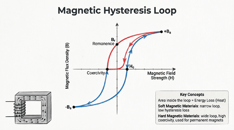
A digital Hall sensor acts as a magnetic switch. It contains a Hall element, a high-gain amplifier, and a Schmitt trigger circuit. The Schmitt trigger provides hysteresis, meaning the sensor has two different magnetic thresholds: one for turning ON and a lower one for turning OFF.
Characteristics:
- Output is binary: either HIGH (e.g., supply voltage) or LOW (e.g., 0V / Ground).
- Operate Point ($B_{OP}$): The magnetic field strength required to turn the output ON.
- Release Point ($B_{RP}$): The magnetic field strength at which the output turns OFF.
- Hysteresis ($B_{HYS}$): The difference between $B_{OP}$ and $B_{RP}$ ($B_{HYS} = B_{OP} – B_{RP}$). This prevents rapid, noisy switching (chatter) when the magnet is near the threshold.
Types of Digital Sensors:
- Unipolar Switch: Activates with one polarity (e.g., South pole) and releases when the field is removed.
- Bipolar Switch (Latch): Activates with one polarity (South) and remains ON until the opposite polarity (North) is applied to reset it.
Applications:
- Speed sensing (counting gear teeth or rotating magnets).
- Proximity detection (laptop lid open/close, door switches).
- Brushless DC (BLDC) motor commutation.
What is the difference between analog and digital Hall sensors?
An analog Hall sensor outputs a continuous voltage proportional to the magnetic field’s strength and polarity. A digital Hall sensor acts as a switch, outputting a binary HIGH or LOW signal, and uses hysteresis to prevent erratic switching near the activation threshold.
Key Characteristics and Parameters
When selecting a Hall Effect sensor for a design, engineers must consider several key parameters:
- Sensitivity ($S$): The change in output voltage per unit of magnetic field (e.g., mV/Gauss or mV/mT). Higher sensitivity means a stronger signal for weak magnetic fields.
- Offset Voltage: The output voltage when the magnetic field is exactly zero. Ideally, this is $V_{CC}/2$ for linear sensors, but manufacturing tolerances cause slight deviations.
- Temperature Drift: The Hall coefficient and semiconductor properties change with temperature, causing sensitivity and offset to drift. High-quality sensors include internal temperature compensation circuits.
- Response Time: The time it takes for the output to react to a change in the magnetic field. Modern Hall sensors have response times in the microsecond ($\mu s$) range, making them suitable for high-speed applications.
- Supply Voltage Range: Typically 3.3V to 5V for logic-level sensors, though industrial sensors may operate up to 24V or 30V.
Practical Applications of Hall Effect Sensors
The robustness and contactless nature of Hall Effect sensors make them ideal for harsh environments and high-reliability applications.
1. Automotive Systems
Modern vehicles contain dozens of Hall sensors:
- Crankshaft and Camshaft Position: Detecting the timing of engine rotation for fuel injection and ignition.
- Wheel Speed Sensors (ABS): Counting teeth on a rotating reluctor ring to detect wheel lockup.
- Seatbelt and Door Ajar Switches: Detecting if a latch is closed via a small embedded magnet.
2. Brushless DC (BLDC) Motors
BLDC motors do not have mechanical brushes to commutate the current. Instead, 3 or more Hall Effect sensors are embedded in the stator. As the permanent magnet rotor spins, the sensors detect its position and send digital signals to the motor controller, which electronically switches the current in the stator coils to maintain continuous rotation.
3. Current Sensing
Hall Effect current sensors measure electrical current without making direct electrical contact with the high-power circuit. The current-carrying conductor is passed through a magnetic core with an air gap. The Hall sensor sits in the air gap, measuring the magnetic field generated by the current. This provides galvanic isolation, protecting low-voltage control electronics from high-voltage power lines.
4. Consumer Electronics and Industrial Automation
- Laptop/Tablet Lid Detection: A magnet in the lid and a Hall sensor in the base trigger sleep mode when closed.
- Flow Meters: A rotor with embedded magnets spins as fluid flows past; a Hall sensor counts the rotations to calculate flow rate.
- Keyboard Switches: High-end mechanical keyboards use Hall Effect switches for adjustable actuation points and infinite durability (no physical contact wear).
Practical Examples and Calculations
Example 1: Calculating Hall Voltage
Problem: A Hall Effect sensor is made from an N-type semiconductor with a thickness of $0.1 \text{ mm}$ and a charge carrier density of $1 \times 10^{23} \text{ m}^{-3}$. A control current of $10 \text{ mA}$ is passed through it, and it is placed in a perpendicular magnetic field of $0.5 \text{ T}$. Calculate the Hall voltage. (Assume $e = 1.6 \times 10^{-19} \text{ C}$).
Solution:
Given:
- $t = 0.1 \text{ mm} = 1 \times 10^{-4} \text{ m}$
- $n = 1 \times 10^{23} \text{ m}^{-3}$
- $I = 10 \text{ mA} = 0.01 \text{ A}$
- $B = 0.5 \text{ T}$
- $e = 1.6 \times 10^{-19} \text{ C}$
Formula:
$V_H = \frac{I \cdot B}{n \cdot t \cdot e}$
Calculation:
Denominator $= (1 \times 10^{23}) \times (1 \times 10^{-4}) \times (1.6 \times 10^{-19})$
Denominator $= 1 \times 1.6 \times 10^{23 – 4 – 19} = 1.6 \times 10^0 = 1.6$
Numerator $= I \cdot B = 0.01 \times 0.5 = 0.005$
$V_H = \frac{0.005}{1.6}$
$V_H = 0.003125 \text{ V} = 3.125 \text{ mV}$
Result: The sensor produces a Hall voltage of 3.125 mV. (Note: In practice, internal amplifiers boost this tiny voltage to a usable level, e.g., 0-5V).
Example 2: Hall Effect Current Sensor
Problem: A Hall Effect current sensor has a sensitivity of $40 \text{ mV/A}$. The sensor output is $2.5 \text{ V}$ when $0 \text{ A}$ is flowing. If the measured output voltage is $3.3 \text{ V}$, what is the current flowing through the conductor?
Solution:
Given:
- Sensitivity ($S$) = $40 \text{ mV/A} = 0.04 \text{ V/A}$
- $V_{offset}$ (at 0A) = $2.5 \text{ V}$
- $V_{measured} = 3.3 \text{ V}$
Step 1: Calculate the change in voltage due to current
$\Delta V = V_{measured} – V_{offset}$
$\Delta V = 3.3 \text{ V} – 2.5 \text{ V} = 0.8 \text{ V}$
Step 2: Calculate the current
$I = \frac{\Delta V}{S}$
$I = \frac{0.8 \text{ V}}{0.04 \text{ V/A}}$
$I = 20 \text{ A}$
Result: A current of 20 Amperes is flowing through the conductor.
The Hall Effect sensor is a masterpiece of solid-state physics applied to practical engineering. By leveraging the Lorentz force to deflect charge carriers, these tiny semiconductor devices can accurately detect the presence, strength, and polarity of magnetic fields without any physical contact.
Key takeaways from this guide:
- The Physics: The Hall Effect occurs when a perpendicular magnetic field deflects moving charge carriers in a conductor, creating a transverse voltage (Hall voltage).
- The Formula: $V_H = \frac{I \cdot B}{n \cdot t \cdot e}$. Hall voltage is proportional to current and magnetic field, and inversely proportional to material thickness and carrier density.
- Analog vs. Digital: Analog sensors provide a continuous voltage proportional to the magnetic field, while digital sensors act as clean, hysteretic switches.
- Hysteresis: Digital Hall switches use Schmitt triggers to create distinct ON and OFF thresholds, preventing erratic output chatter in noisy magnetic environments.
- Applications: Hall sensors are critical in automotive systems (ABS, engine timing), BLDC motor commutation, galvanically isolated current sensing, and consumer proximity detection.
Because they have no moving parts, Hall Effect sensors offer unparalleled reliability, long lifespans, and immunity to environmental contaminants. As electric vehicles, renewable energy systems, and advanced robotics continue to grow, the demand for precise, robust magnetic sensing provided by Hall Effect technology will only continue to accelerate.