The Toggle Flip-flop
The Toggle (T) Flip-Flop: Complete Guide to Frequency Division and Counting
Introduction to the Toggle Flip-Flop
In the realm of sequential digital logic, the Toggle (T) Flip-Flop is the ultimate minimalist. While the JK flip-flop is the “universal” workhorse and the D flip-flop is the standard for data storage, the T flip-flop is specifically designed for one highly specialized, incredibly useful task: toggling its output state.
When its input is activated, the T flip-flop simply flips its output to the opposite logic level on every clock pulse. This simple “flip-flop” action makes it the fundamental building block for frequency division and binary counting. Every time you look at a digital clock, use a computer, or interact with a microcontroller, T flip-flops (or circuits mimicking their behavior) are silently dividing clock frequencies and counting events in the background.
Although dedicated T flip-flop integrated circuits are rare in modern commercial IC catalogs (engineers usually just wire a JK or D flip-flop to act like a T flip-flop), the concept of the T flip-flop is absolutely central to digital design.
This comprehensive guide will explore the architecture, truth table, characteristic equation, and practical applications of the Toggle flip-flop, complete with visual diagrams and real-world examples.
What is a Toggle (T) Flip-Flop?
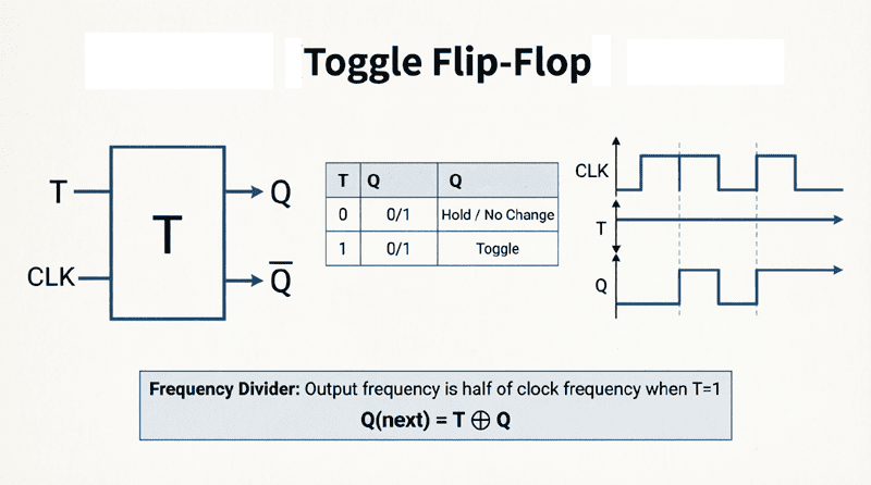
A Toggle (T) Flip-Flop is a sequential logic circuit with a single input (T). When T=0, the output holds its current state. When T=1, the output toggles (switches to the opposite logic level) on the active edge of the clock signal. It is primarily used for frequency division and building binary counters.
Understanding the Toggle Action
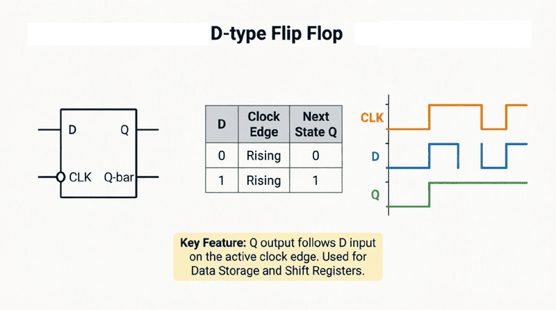
To understand the T flip-flop, we must look at its behavior over time. Unlike a D flip-flop, which blindly copies its input to the output, a T flip-flop looks at its own current state to determine its next state.
The Two Modes of Operation
- Hold Mode (T = 0):
When the Toggle input is LOW, the flip-flop ignores the clock pulses. The output $Q$ remains exactly as it was. This is the “memory” or “hold” state. - Toggle Mode (T = 1):
When the Toggle input is HIGH, the flip-flop enters toggle mode. On every active clock edge (rising or falling), the output $Q$ switches to its complement ($Q’$). If it was 1, it becomes 0. If it was 0, it becomes 1.
This continuous toggling when T=1 is what gives the flip-flop its name.
Truth Table and Characteristic Equation
The behavior of the T flip-flop is defined by its truth table and its characteristic equation, which mathematically describes the next state ($Q_{n+1}$) based on the current state ($Q_n$) and the input ($T$).
Truth Table
| Clock | T (Toggle) | $Q_n$ (Current State) | $Q_{n+1}$ (Next State) | Operation |
|---|---|---|---|---|
| ↑ | 0 | 0 | 0 | Hold |
| ↑ | 0 | 1 | 1 | Hold |
| ↑ | 1 | 0 | 1 | Toggle |
| ↑ | 1 | 1 | 0 | Toggle |
(Note: “↑” represents the active clock edge).
Characteristic Equation
The characteristic equation is derived from the truth table using Boolean algebra or a Karnaugh map. It defines the next state mathematically:
$Q_{n+1} = T \oplus Q_n$
Where $\oplus$ represents the XOR (Exclusive OR) operation.
Expanded, this equation is:
$Q_{n+1} = T\overline{Q_n} + \overline{T}Q_n$
This equation perfectly captures the logic: if T is 1, the next state is the inverse of the current state ($\overline{Q_n}$). If T is 0, the next state is the same as the current state ($Q_n$).
What is the characteristic equation of a T Flip-Flop?
The characteristic equation is $Q_{n+1} = T \oplus Q_n$ (T XOR Q). This means the next state is the XOR of the Toggle input and the current state, mathematically proving that the output toggles when T=1 and holds when T=0.
Internal Structure and Implementation
Interestingly, you rarely find a dedicated “T Flip-Flop” IC on a supplier’s shelf. Instead, digital engineers construct a T flip-flop using the more common JK or D flip-flops by adding simple external logic gates.
1. Implementing T from a JK Flip-Flop
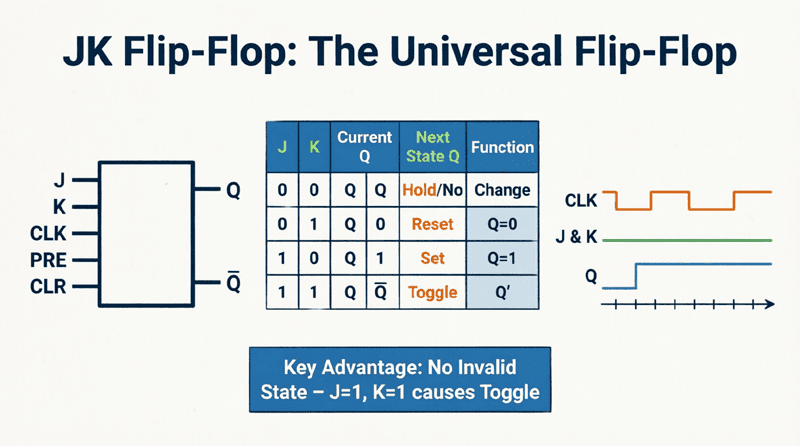
This is the easiest and most common method. Recall that a JK flip-flop toggles its output when both J and K inputs are HIGH.
- To make a JK flip-flop act like a T flip-flop, simply tie the J and K inputs together and use this common connection as the T input.
- When T=0, both J and K are 0 (Hold mode).
- When T=1, both J and K are 1 (Toggle mode).
2. Implementing T from a D Flip-Flop
To make a D flip-flop toggle, the D input must be the exact opposite of the current Q output when T=1.
- We achieve this by feeding the Q output through an XOR gate along with the T input.
- The output of the XOR gate is connected to the D input.
- When T=0, $D = 0 \oplus Q = Q$ (Hold mode).
- When T=1, $D = 1 \oplus Q = Q’$ (Toggle mode).
Frequency Division: The Divide-by-2 Circuit
The most famous application of the T flip-flop is frequency division. When a T flip-flop is configured in permanent toggle mode (T tied permanently to Logic 1 or VCC), it acts as a Divide-by-2 circuit.
How Frequency Division Works
Imagine you feed a 10 MHz square wave clock signal into a T flip-flop with T=1.
- On the 1st clock pulse, Q goes HIGH.
- On the 2nd clock pulse, Q goes LOW.
- On the 3rd clock pulse, Q goes HIGH.
- On the 4th clock pulse, Q goes LOW.
It takes exactly two input clock pulses for the output Q to complete one full cycle (HIGH to LOW and back to HIGH). Therefore, the output frequency is exactly half of the input frequency.
$f_{out} = \frac{f_{in}}{2}$
This principle is the absolute foundation of digital clock generation. By cascading multiple T flip-flops (connecting the Q output of the first to the clock input of the second), you can divide the frequency by 4, 8, 16, 32, and so on.
How does a T Flip-Flop divide frequency?
When the T input is held HIGH (T=1), the flip-flop toggles its output on every clock pulse. Because it takes two clock pulses for the output to complete one full HIGH-LOW cycle, the output frequency is exactly half of the input clock frequency ($f_{out} = f_{in} / 2$).
Building Binary Counters (Ripple Counters)
By cascading T flip-flops, we can build Asynchronous Binary Counters, commonly known as Ripple Counters.
The 4-Bit Ripple Counter
If we connect four T flip-flops in a chain, with the Q output of each stage driving the clock input of the next stage, and all T inputs tied HIGH, we create a 4-bit counter.
- Stage 0 (LSB): Toggles on every input clock pulse. (Divides by 2)
- Stage 1: Toggles every time Stage 0 transitions from 1 to 0. (Divides by 4)
- Stage 2: Toggles every time Stage 1 transitions from 1 to 0. (Divides by 8)
- Stage 3 (MSB): Toggles every time Stage 2 transitions from 1 to 0. (Divides by 16)
The outputs $Q_3 Q_2 Q_1 Q_0$ will count in binary from 0000 to 1111 (0 to 15 in decimal), and then roll over back to 0000.
Because the clock signal “ripples” through the chain of flip-flops, there is a slight cumulative propagation delay. While this makes ripple counters unsuitable for very high-speed applications, they are incredibly simple, require no complex combinational logic, and are perfect for low-speed counting, digital clocks, and frequency division.
Practical Applications of the T Flip-Flop
While often implemented using JK or D flip-flops, the functionality of the T flip-flop is ubiquitous in digital systems.
1. Digital Clocks and Timers
Digital clocks rely on a high-frequency crystal oscillator (e.g., 32,768 Hz). A chain of T flip-flops (frequency dividers) is used to divide this high frequency down to exactly 1 Hz (one pulse per second) to drive the seconds counter. Further division creates the minutes and hours.
2. Event Counters
In industrial automation, T flip-flop chains are used to count physical events, such as items passing on a conveyor belt. A sensor generates a pulse for each item, and the ripple counter tallies the total number of items.
3. Control Logic and State Machines
In Finite State Machines (FSMs), a T flip-flop is used when a system needs to alternate between two states (e.g., a blinking LED, a motor reversing direction, or a toggle switch in software).
4. Pseudo-Random Number Generators
When combined with XOR feedback gates (Linear Feedback Shift Registers), T flip-flops can generate pseudo-random binary sequences used in cryptography, spread-spectrum communications, and testing.
Advantages and Limitations
Advantages
- Simplicity: Requires only one control input (T).
- Efficiency for Counting: The most natural and efficient flip-flop for binary counting and frequency division.
- Glitch-Free: Like the JK flip-flop, it avoids the forbidden state of the SR flip-flop.
Limitations
- No Direct Data Loading: Unlike the D flip-flop, you cannot easily “load” a specific 1 or 0 into a T flip-flop without complex external logic. It is strictly for toggling or holding.
- Propagation Delay in Ripple Counters: In asynchronous ripple counters, the delay accumulates through each stage, limiting the maximum operating frequency. (This is solved by using Synchronous counters, where all T flip-flops share the same clock, but their T inputs are controlled by AND gates).
The Toggle (T) Flip-Flop is the embodiment of simplicity in sequential logic. By reducing the complex control inputs of the JK flip-flop to a single Toggle line, it provides a highly specialized, robust mechanism for alternating states.
While you may not buy a dedicated “T Flip-Flop” chip, the T flip-flop’s architecture—whether built from a JK or D flip-flop—is the fundamental engine behind every digital counter, frequency divider, and clock generation circuit in existence.
Key takeaways from this guide include:
- Single Input Operation: T=0 holds the state; T=1 toggles the state on the clock edge.
- Characteristic Equation: $Q_{n+1} = T \oplus Q_n$ (XOR logic).
- Implementation: Easily built by tying J=K=T on a JK flip-flop, or using an XOR gate on a D flip-flop.
- Frequency Division: A T flip-flop with T=1 divides the input clock frequency exactly in half.
- Binary Counting: Cascading T flip-flops creates ripple counters, the foundation of digital counting systems.