Mutual Inductance
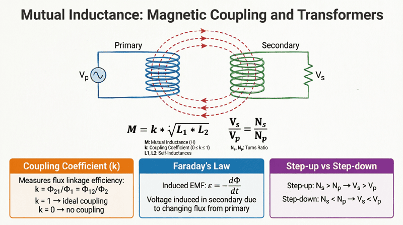
Complete Guide to Magnetic Coupling and Transformers
Introduction to Mutual Inductance
A single coil of wire can induce a voltage in itself when its current changes—a property known as self-inductance. But what happens when we place a second coil nearby? If the magnetic field generated by the first coil expands and collapses, it doesn’t just interact with its own turns; it also cuts across the turns of the neighboring coil. This interaction induces a voltage in the second coil, even though there is no direct electrical connection between them.
This phenomenon is called mutual inductance. It is the foundational principle behind some of the most important electrical devices in the world, including transformers, electric motors, generators, and modern wireless charging pads.
Mutual inductance allows electrical energy to be transferred from one circuit to another purely through magnetic fields. Understanding how coils interact, how to measure their coupling, and how to calculate the induced voltages is essential for anyone working with power systems, telecommunications, or electronic circuit design. This comprehensive guide will explore the physics, mathematics, and practical applications of mutual inductance.
What is Mutual Inductance?
Mutual inductance is the property where a change in current in one coil induces a voltage in a nearby second coil through a shared magnetic field. It is measured in Henrys (H) and is the fundamental operating principle of transformers and inductive wireless power transfer.
The Physics of Magnetic Coupling
To understand mutual inductance, we must look at the behavior of magnetic flux. When an alternating current (AC) flows through a primary coil (Coil 1), it generates a magnetic field. The total magnetic flux produced by this coil is denoted as $\Phi_1$.
However, not all of this magnetic flux links with a secondary coil (Coil 2) placed nearby. The flux is divided into two parts:
- Leakage Flux ($\Phi_{l1}$): The portion of the magnetic flux that completes its path through the air without passing through the second coil.
- Mutual Flux ($\Phi_{12}$): The portion of the magnetic flux that successfully passes through (or “links”) the second coil.
According to Faraday’s Law of Electromagnetic Induction, a changing magnetic flux induces an electromotive force (EMF). Therefore, the mutual flux ($\Phi_{12}$) changing over time induces a voltage across the terminals of Coil 2. This induced voltage is called the mutually induced EMF.
The magnitude of this induced voltage depends on two things:
- The rate at which the current in Coil 1 is changing ($di_1/dt$).
- The mutual inductance ($M$) between the two coils.
Mathematically, the mutually induced EMF in Coil 2 ($e_2$) is expressed as:
$e_2 = -M \frac{di_1}{dt}$
Where:
- $e_2$ = Mutually induced voltage in Coil 2 (Volts)
- $M$ = Mutual inductance between the coils (Henrys)
- $\frac{di_1}{dt}$ = Rate of change of current in Coil 1 (Amperes per second)
- The negative sign (-) = Indicates that the induced voltage opposes the change in the primary current (Lenz’s Law).
What causes mutual inductance?
Mutual inductance is caused by the magnetic flux generated by one coil physically passing through (linking with) a second nearby coil. When the current in the first coil changes, the shared magnetic flux changes, inducing a voltage in the second coil via Faraday’s Law of Induction.
Factors Affecting Mutual Inductance
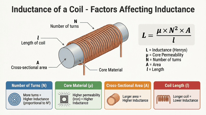
Just as the self-inductance of a single coil depends on its physical construction, the mutual inductance between two coils depends on their physical relationship and geometry. The key factors include:
1. Number of Turns ($N_1$ and $N_2$)
The mutual inductance is directly proportional to the product of the number of turns in both coils. More turns in either the primary or secondary coil mean more wire is available to generate or capture the magnetic flux, increasing $M$.
2. Distance and Orientation
The physical distance between the coils drastically affects mutual inductance. As the coils are moved further apart, the amount of mutual flux ($\Phi_{12}$) decreases rapidly, and leakage flux increases. Additionally, the physical orientation matters; coils aligned on the same axis share maximum flux, while coils placed at 90-degree angles to each other share almost zero flux.
3. Core Material and Size
If both coils are wound around a shared magnetic core (like laminated iron or ferrite), the core guides the magnetic flux, forcing almost all of it to pass through both coils. This drastically reduces leakage flux and maximizes mutual inductance. The permeability ($\mu$) and cross-sectional area ($A$) of the core directly increase $M$.
The Coefficient of Coupling ($k$)
In the real world, it is impossible to get 100% of the magnetic flux from one coil to link with the other. There is always some leakage. To quantify how effectively two coils are magnetically coupled, engineers use the Coefficient of Coupling, denoted by the letter $k$.
The coefficient of coupling is a dimensionless ratio ranging from 0 to 1:
- $k = 0$: No magnetic coupling. The coils are infinitely far apart or perfectly shielded.
- $k = 1$: Perfect (or ideal) coupling. 100% of the flux from Coil 1 links with Coil 2. (This is a theoretical ideal; in reality, $k$ is always less than 1).
Calculating Mutual Inductance using $k$
The mutual inductance ($M$) can be easily calculated if you know the self-inductances of the two coils ($L_1$ and $L_2$) and their coefficient of coupling ($k$):
$M = k \sqrt{L_1 \times L_2}$
Where:
- $M$ = Mutual inductance in Henrys (H)
- $k$ = Coefficient of coupling (0 to 1)
- $L_1$ = Self-inductance of Coil 1 in Henrys (H)
- $L_2$ = Self-inductance of Coil 2 in Henrys (H)
Tightly Coupled vs. Loosely Coupled Coils
- Tightly Coupled ($k > 0.8$): The coils share a high-permeability core (like a power transformer). Almost all flux is mutual flux. Used in power distribution and voltage conversion.
- Loosely Coupled ($k < 0.5$): The coils are separated by air or a large distance (like an air-core RF transformer or a wireless charging pad). Significant leakage flux exists. Used in radio tuning circuits and wireless power transfer.
What is the Coefficient of Coupling ($k$)?
The coefficient of coupling ($k$) is a ratio between 0 and 1 that represents the fraction of magnetic flux from one coil that successfully links with a second coil. It is used to calculate mutual inductance using the formula $M = k\sqrt{L_1 L_2}$.
Practical Calculation Example
Let’s apply the coefficient of coupling formula to a real-world scenario.
Problem:
Two coils are wound on a shared ferrite core. Coil 1 has a self-inductance of $L_1 = 100 \text{ mH}$ (0.1 H). Coil 2 has a self-inductance of $L_2 = 400 \text{ mH}$ (0.4 H). Due to the high-quality ferrite core, the coefficient of coupling is $k = 0.95$. Calculate the mutual inductance ($M$) between the two coils.
Solution:
Given:
- $L_1 = 0.1 \text{ H}$
- $L_2 = 0.4 \text{ H}$
- $k = 0.95$
Formula:
$M = k \sqrt{L_1 \times L_2}$
Step 1: Multiply the inductances
$L_1 \times L_2 = 0.1 \times 0.4 = 0.04 \text{ H}^2$
Step 2: Take the square root
$\sqrt{0.04} = 0.2 \text{ H}$
Step 3: Multiply by the coefficient of coupling
$M = 0.95 \times 0.2$
$M = 0.19 \text{ H}$ (or 190 mH)
Result: The mutual inductance between the two coils is 190 millihenrys.
The Dot Convention: Determining Polarity
When analyzing circuits with mutually coupled coils, it is crucial to know the polarity of the mutually induced voltage. Does the induced voltage add to the self-induced voltage, or does it subtract from it?
Because we cannot physically see the direction the wire is wound inside a transformer or inductor, electrical schematics use the Dot Convention to indicate the relative winding directions.
How the Dot Convention Works
A small dot is placed on one terminal of each mutually coupled coil. The dots indicate terminals that have the same instantaneous polarity.
Rule 1: Current entering the dotted terminal
If current enters the dotted terminal of Coil 1, it induces a voltage in Coil 2 that is positive at the dotted terminal of Coil 2.
Rule 2: Current leaving the dotted terminal
If current leaves the dotted terminal of Coil 1, the induced voltage in Coil 2 is negative at the dotted terminal (or positive at the undotted terminal).
Series Aiding vs. Series Opposing
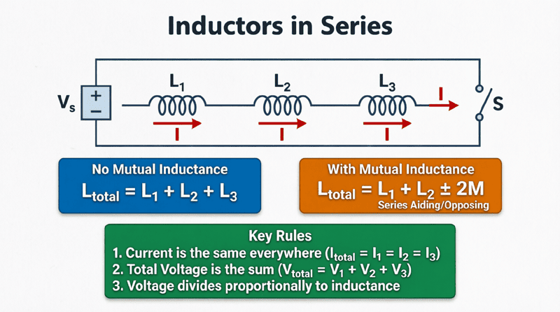
When two mutually coupled coils are connected in series, the dots tell us how to calculate the total equivalent inductance ($L_{eq}$).
1. Series Aiding (Cumulative Coupling):
If the current enters the dotted terminal of Coil 1 and also enters the dotted terminal of Coil 2, the magnetic fields of the two coils reinforce each other. The mutual inductance adds to the total inductance.
$L_{eq} = L_1 + L_2 + 2M$
2. Series Opposing (Differential Coupling):
If the current enters the dotted terminal of Coil 1 but leaves the dotted terminal of Coil 2, the magnetic fields oppose each other. The mutual inductance subtracts from the total inductance.
$L_{eq} = L_1 + L_2 – 2M$
Understanding the dot convention is mandatory for correctly analyzing transformer circuits, coupled inductors in power supplies, and RF filters.
Practical Applications of Mutual Inductance
The ability to transfer energy and signals across an air gap or through a magnetic core without direct electrical contact has revolutionized electrical engineering.
1. Electrical Transformers
The most common and vital application of mutual inductance is the electrical transformer. By winding a primary and secondary coil around a highly permeable iron core (achieving $k \approx 0.99$), transformers can efficiently step up voltage for long-distance power transmission or step down voltage for safe residential use. The voltage ratio is directly proportional to the turns ratio ($V_1/V_2 = N_1/N_2$).
2. Wireless Power Transfer (Inductive Charging)
Modern wireless charging pads for smartphones and electric toothbrushes rely on loose magnetic coupling. An alternating current in the transmitter coil (inside the charging pad) generates a changing magnetic field. This field links with the receiver coil (inside the phone), inducing a voltage that is then rectified to charge the battery. Because the coupling is loose ($k$ is often between 0.2 and 0.5), these systems require precise tuning and high frequencies to transfer power efficiently.
3. Induction Motors
In an AC induction motor, the stator (stationary part) contains coils that generate a rotating magnetic field. This rotating flux cuts across the conductive bars of the rotor (the rotating part). Through mutual induction, a voltage is induced in the rotor bars, causing current to flow. This rotor current generates its own magnetic field, which interacts with the stator’s field to produce mechanical torque.
4. Telemetry and Sensors
Mutual inductance is used in various non-contact sensors. For example, Linear Variable Differential Transformers (LVDTs) use a movable magnetic core inside three coils to precisely measure linear displacement. As the core moves, it changes the mutual inductance between the primary and secondary coils, producing a voltage output proportional to the physical movement.
5. Radio Frequency (RF) Tuning
In older radio receivers and modern RF circuits, loosely coupled air-core transformers are used to transfer signals between amplifier stages while providing impedance matching. By adjusting the distance between the coils or using a variable ferrite slug, engineers can tune the mutual inductance to optimize signal transfer at specific frequencies.
Mutual inductance expands the concept of electromagnetic induction from a single isolated coil to interacting systems. By understanding how magnetic flux links between two circuits, engineers can design devices that transfer energy and information without physical electrical connections.
Key takeaways from this guide include:
- Definition: Mutual inductance ($M$) is the induction of a voltage in one coil due to a changing current in a nearby coil. It is measured in Henrys (H).
- Magnetic Flux: It relies on the “mutual flux” ($\Phi_{12}$) that successfully links both coils, while “leakage flux” represents lost magnetic energy.
- Coefficient of Coupling ($k$): A value between 0 and 1 that defines the efficiency of the magnetic link. $M = k\sqrt{L_1 L_2}$.
- Dot Convention: A schematic standard used to determine the relative polarity of induced voltages, crucial for calculating whether coupled inductors in series are “aiding” ($+2M$) or “opposing” ($-2M$).
- Applications: It is the foundational physics behind power transformers, wireless charging, induction motors, and non-contact sensors.
Mutual inductance bridges the gap between isolated circuits, allowing for the safe, efficient, and wireless transfer of electrical power. As we move forward in this series, we will explore how to combine multiple inductors within a single circuit, looking next at the rules for connecting Inductors in Series.