Inductors in Series
Complete Guide to Equivalent Inductance and Mutual Coupling
Introduction to Inductors in Series
In electrical and electronic circuit design, it is very common to connect multiple components together to achieve a specific electrical characteristic that a single component cannot provide. Just as resistors and capacitors can be connected in series to alter total resistance or capacitance, inductors can be connected in series to achieve a desired total inductance.
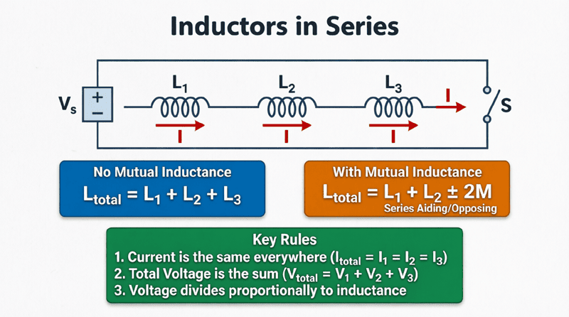
When inductors are connected in series, they are arranged in a single, continuous path so that the exact same electrical current flows through each of them sequentially. However, calculating the total (or equivalent) inductance of this combination is not always as simple as just adding the numbers together. If the inductors are placed close enough together that their magnetic fields interact, mutual inductance comes into play, fundamentally changing the total inductance of the circuit.
Understanding how to calculate the equivalent inductance of series-connected coils—both with and without magnetic coupling—is a critical skill for designing filters, power supplies, transformers, and RF circuits. This comprehensive guide will explore the physics, mathematical derivations, and practical calculations for inductors connected in series.
How do you calculate inductors in series?
If there is no magnetic coupling between the inductors, the total equivalent inductance is simply the sum of the individual inductances: $L_{eq} = L_1 + L_2 + L_3 + …$. If they are magnetically coupled, you must add or subtract twice the mutual inductance ($2M$) depending on whether their magnetic fields aid or oppose each other.
Inductors in Series Without Mutual Inductance
Let’s start with the simplest scenario: multiple inductors connected in series where they are physically spaced far apart, or magnetically shielded, so that their magnetic fields do not interact. In this case, the mutual inductance ($M$) between them is zero.
The Physics of Series Inductors
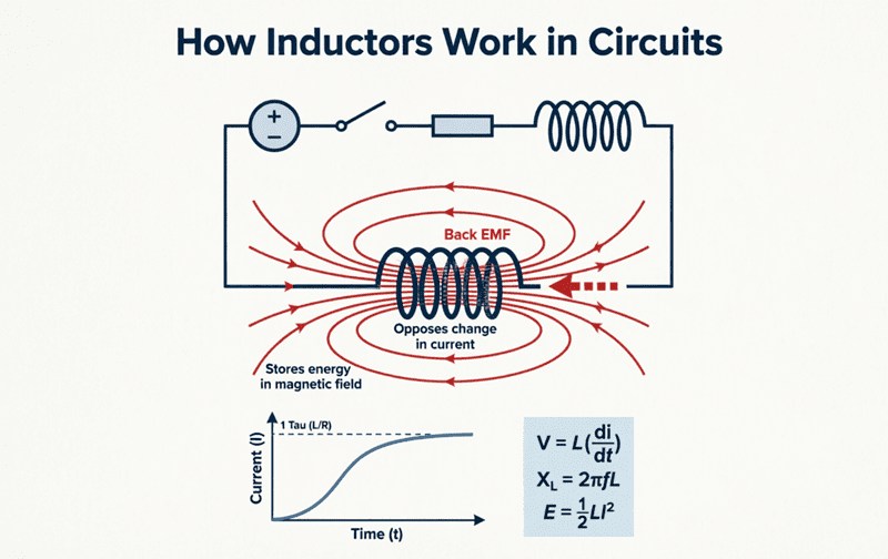
When a changing current ($di/dt$) flows through a series circuit, that exact same rate of change applies to every inductor in the chain. According to Faraday’s Law, each inductor will generate a self-induced voltage (Back EMF) proportional to its own inductance:
- Voltage across Inductor 1: $V_1 = L_1 \frac{di}{dt}$
- Voltage across Inductor 2: $V_2 = L_2 \frac{di}{dt}$
- Voltage across Inductor 3: $V_3 = L_3 \frac{di}{dt}$
According to Kirchhoff’s Voltage Law (KVL), the total voltage ($V_{total}$) across the series combination is the sum of the individual voltage drops:
$V_{total} = V_1 + V_2 + V_3$
If we substitute the individual voltage equations into KVL, we get:
$V_{total} = L_1 \frac{di}{dt} + L_2 \frac{di}{dt} + L_3 \frac{di}{dt}$
We can factor out the common $\frac{di}{dt}$ term:
$V_{total} = (L_1 + L_2 + L_3) \frac{di}{dt}$
By definition, the total voltage across an equivalent single inductor ($L_{eq}$) is $V_{total} = L_{eq} \frac{di}{dt}$. Therefore, by comparing the two equations, we arrive at the fundamental formula for uncoupled series inductors:
$L_{eq} = L_1 + L_2 + L_3 + … + L_n$
Practical Calculation Example
Problem: Three inductors with values of 10 mH, 22 mH, and 33 mH are connected in series. There is no magnetic coupling between them. Calculate the total equivalent inductance.
Solution:
$L_{eq} = 10\text{mH} + 22\text{mH} + 33\text{mH}$
$L_{eq} = 65\text{ mH}$
Do inductors add up in series?
Yes. When inductors are connected in series without any mutual magnetic coupling, their inductances simply add together, exactly like resistors in series. The total inductance is always greater than the largest individual inductor in the chain.
Inductors in Series WITH Mutual Inductance
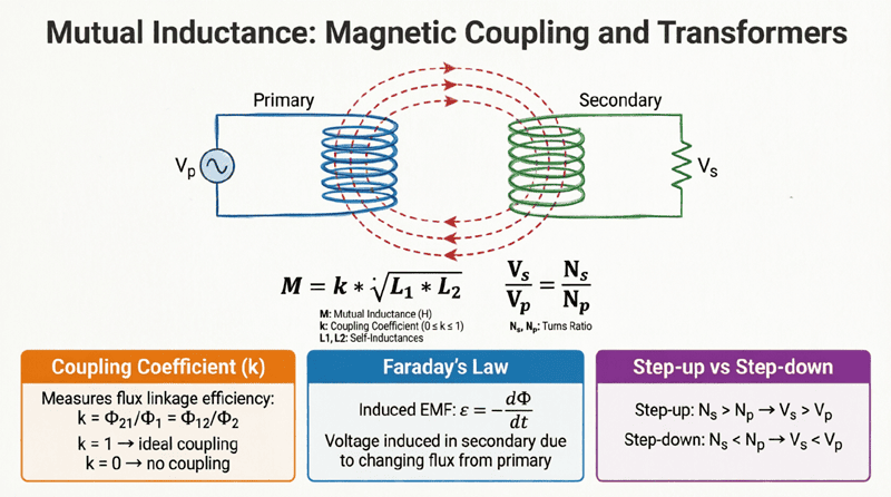
In the real world, if two inductors are placed close to each other in a series circuit, the magnetic field generated by the first coil will link with the second coil, and vice versa. This creates mutual inductance ($M$), which induces an additional voltage in each coil.
To calculate the total inductance when mutual inductance is present, we must know the physical orientation of the coils. This is determined by the dot convention (explained in Mutual Inductance). Depending on how the coils are wound and connected, their magnetic fields will either reinforce each other or cancel each other out.
1. Series Aiding Connection (Cumulative Coupling)
In a series aiding configuration, the inductors are connected such that the current enters the dotted terminal of the first coil and also enters the dotted terminal of the second coil.
Because the current flows in the same relative direction through both coils, their individual magnetic fields point in the same direction and reinforce (aid) each other. The mutual inductance effectively increases the total opposition to the changing current.
The formula for the total equivalent inductance in a series aiding connection is:
$L_{eq} = L_1 + L_2 + 2M$
Why $2M$? The mutual flux induces a voltage in Coil 2 due to Coil 1’s current, AND it induces a voltage in Coil 1 due to Coil 2’s current. Therefore, the mutual inductance effect is counted twice.
2. Series Opposing Connection (Differential Coupling)
In a series opposing configuration, the inductors are connected such that the current enters the dotted terminal of the first coil but leaves the dotted terminal of the second coil.
In this arrangement, the magnetic fields generated by the two coils point in opposite directions and oppose (cancel) each other. The mutual inductance effectively decreases the total opposition to the changing current.
The formula for the total equivalent inductance in a series opposing connection is:
$L_{eq} = L_1 + L_2 – 2M$
Practical Calculation Example with Mutual Inductance
Problem: Two inductors, $L_1 = 40 \text{ mH}$ and $L_2 = 60 \text{ mH}$, are connected in series. They are magnetically coupled with a mutual inductance of $M = 10 \text{ mH}$. Calculate the total equivalent inductance for both the series aiding and series opposing configurations.
Solution for Series Aiding:
$L_{eq(aid)} = L_1 + L_2 + 2M$
$L_{eq(aid)} = 40 + 60 + 2(10)$
$L_{eq(aid)} = 100 + 20$
$L_{eq(aid)} = 120 \text{ mH}$
Solution for Series Opposing:
$L_{eq(opp)} = L_1 + L_2 – 2M$
$L_{eq(opp)} = 40 + 60 – 2(10)$
$L_{eq(opp)} = 100 – 20$
$L_{eq(opp)} = 80 \text{ mH}$
Observation: The physical orientation of the coils changes the total circuit inductance by 40 mH! This principle is actually used in variable inductors and certain types of RF tuning circuits.
What is the difference between series aiding and series opposing inductors?
In series aiding, the magnetic fields of the coupled coils reinforce each other, increasing total inductance ($L_{eq} = L_1 + L_2 + 2M$). In series opposing, the magnetic fields cancel each other out, decreasing total inductance ($L_{eq} = L_1 + L_2 – 2M$).
Voltage Division in Series Inductors
Just as resistors in series divide the total voltage proportionally to their resistance, inductors in series divide the total voltage proportionally to their inductance. This is highly relevant in high-frequency circuits, snubber networks, and when dealing with voltage spikes.
Because the same changing current ($di/dt$) flows through all series inductors, the voltage drop across any specific inductor ($V_x$) is directly proportional to its inductance ($L_x$) relative to the total equivalent inductance ($L_{eq}$).
The Voltage Division Formula:
$V_x = V_{total} \times \frac{L_x}{L_{eq}}$
Voltage Division Example
Problem: A rapidly switching circuit generates a total voltage spike of 50V across two uncoupled inductors in series. $L_1 = 2 \text{ mH}$ and $L_2 = 8 \text{ mH}$. Calculate the voltage drop across each inductor.
Solution:
First, find $L_{eq}$:
$L_{eq} = 2\text{mH} + 8\text{mH} = 10\text{ mH}$
Voltage across $L_1$:
$V_1 = 50\text{V} \times \frac{2\text{mH}}{10\text{mH}} = 50 \times 0.2 = \mathbf{10\text{V}}$
Voltage across $L_2$:
$V_2 = 50\text{V} \times \frac{8\text{mH}}{10\text{mH}} = 50 \times 0.8 = \mathbf{40\text{V}}$
Verification: $10\text{V} + 40\text{V} = 50\text{V}$. The larger inductor takes the larger share of the voltage spike.
Practical Considerations for Series Inductors
When designing real-world circuits with series inductors, engineers must look beyond the ideal mathematical formulas and consider physical limitations.
1. Current Rating (The Weakest Link)
Inductors have a maximum current rating, dictated by the thickness of the wire (to prevent overheating) and the core material (to prevent magnetic saturation). When inductors are connected in series, the exact same current flows through all of them. Therefore, the maximum safe current for the entire series chain is limited by the inductor with the lowest current rating.
2. DC Resistance (DCR) Adds Up
Every physical inductor is made of wire, which has inherent DC resistance. When you connect inductors in series, their DC resistances add together just like their inductances:
$R_{total} = R_{DCR1} + R_{DCR2} + … + R_{DCRn}$
In power supply applications, a high total DCR will cause unwanted voltage drops and $I^2R$ power losses (heat). Engineers must balance the need for higher inductance against the penalty of increased resistance.
3. Parasitic Capacitance and Self-Resonant Frequency (SRF)
As discussed in previous articles, every inductor has parasitic capacitance. When you connect inductors in series, the total parasitic capacitance of the chain actually decreases (similar to capacitors in series). However, the total inductance increases. Because the Self-Resonant Frequency is calculated as $f_r = \frac{1}{2\pi\sqrt{LC}}$, increasing $L$ while decreasing $C$ will drastically lower the SRF of the combined component. This means a series combination of inductors will stop behaving like an inductor at a much lower frequency than the individual components would on their own.
Connecting inductors in series is a straightforward way to increase the total inductance of a circuit, but it requires careful attention to how the components interact magnetically. While uncoupled inductors simply add together, coupled inductors introduce the complex variables of mutual inductance, requiring engineers to account for series aiding and series opposing configurations.
Key takeaways from this guide include:
- Uncoupled Series Inductors: Total inductance is the simple sum of individual values ($L_{eq} = L_1 + L_2 + …$).
- Coupled Series Inductors: Mutual inductance ($M$) must be considered.
- Series Aiding: Magnetic fields reinforce, adding $2M$ to the total ($L_{eq} = L_1 + L_2 + 2M$).
- Series Opposing: Magnetic fields cancel, subtracting $2M$ from the total ($L_{eq} = L_1 + L_2 – 2M$).
- Voltage Division: Voltage drops across series inductors are proportional to their inductance values relative to the total equivalent inductance.
- Real-World Limits: The current rating of a series chain is limited by the weakest inductor, and the total DC resistance (DCR) is the sum of all individual resistances.
Understanding how inductors behave in series provides the necessary foundation for analyzing complex RLC networks, designing multi-stage filters, and building efficient power conversion circuits. In our next article, we will flip the topology and explore how to calculate equivalent inductance when components are connected Inductors in Parallel.